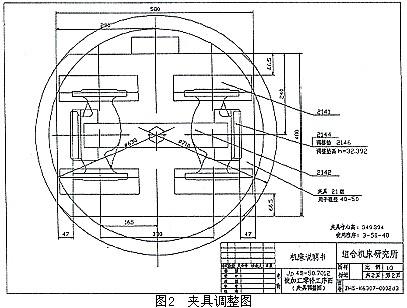
Abstract: Combining several application examples, the importance, necessity, superiority and development prospect of CAD in the design of machining center and flexible line scheme are emphasized. The design of the scheme referred to in this paper mainly refers to the design of the application engineering (including the design of the project during the project bidding process). Both machining centers and flexible lines are used for multi-species processing. Its characteristics are that there are many kinds of parts and large changes in the process, and the workload of the design is much larger than that of the general combined machine tool. With traditional manual design methods, it takes a lot of manpower and time, which is often difficult to complete in the required time. If you introduce CAD technology and use its strengths, the effect will be very significant. In this regard, we have done some work and made preliminary application attempts. Table 1 Valve body classification table kind Three links Four links pressure 6 16 40 64 16 40 64 The way to  ∨ ∨ ∨ ∨ ∨ ∨ ∨  ∨ ∨ ∨ ∨ ∨ ∨ ∨  ∨ ∨ ∨ ∨ ∨ ∨ ∨  ∨ ∨ ∨ ∨ ∨ ∨ ∨  ∨ ∨ ∨ ∨ ∨ ∨ ∨  ∨ ∨ ∨ ∨ ∨ ∨ ∨  ∨ ∨ ∨ ∨ ∨ ∨ ∨ Which kind of valve body is machined by the machine depends entirely on the order, so the variety is frequently changed during the production process. Sometimes the order quantity of a valve is only a few pieces, and each time you change the type, you need to replace or adjust the fixture, tool, program, etc. Their process diagram, processing diagram, fixture adjustment diagram, etc. must be complete and clear to ensure operation. The staff worked smoothly. With 49 different parts, the design work is heavy. We introduced CAD technology, first made various modules according to actual needs, and then drawn the fixture adjustment map and processing schematics required for various parts. The time required is greatly reduced, and the quality of the map is greatly improved. 2) Draw the fixture adjustment chart (Figure 2) The figure shows that the jig selected for processing the valve body JP40-50 is 21 sets of jigs. Two parts can be mounted on each fixture. The selected adjustment pad is 2146 (32.392 height) and the V-shaped blocks positioned at both ends are adjusted to 66.5 from the edge of the clamp. The 21 sets of clamps can be used for three-way valve bodies with a diameter of 40 and 50 (a total of 8 types). The figure also shows that the part number of the CNC should be recalled when machining the valve body is 3-50-40. The operator will select and adjust the fixture according to this diagram. If you change the variety, just replace the adjustment pad and change the distance of the positioned V-block to the edge of the clamp. The figure shows one of the 49 parts (valve body JP40-50), a 50-way three-way valve body with a pressure of 4 MPa and three outer flanges. The thick solid line in the figure shows The faces and holes required to be machined, and the dimensions and tolerances to be machined are indicated. The 7th thread milling thread is usually used for threading on the FMC. As shown in Fig. 4, a different diameter of the thread can be milled by a planetary milling method with a 30 comb (in the figure). For M64×1.5), the trajectory of the tool center is shown in the left figure of the figure, divided into 1 to 5 segments. The first section of the tool is fed laterally from the center of the hole to R30.688, and the second section is fed to R32.212 in the 90° area. At this point, the cutting of the tool has been completed, and the third segment is within 360°. After completing the planetary milling one week, paragraphs 4 and 5 are exits. Since the thread comb is a new type of tool, in order to facilitate the operator and the field technician to understand the program, draw a cycle diagram of the knife. Since each part has four different materials, such as cast iron, cast steel, and stainless steel, the drawings are filled with several different cutting amounts. Figures 5 and 6 show a schematic view of machining of a part on a machining center. The figure shows the location, dimensions and accuracy of the machine, the positioning method and the selected tool. For the 16 machine tools in the flexible line, for 6 kinds of reducers, such a picture needs about 100 sheets (some processes are longer, one picture is not enough, for example, Figure 5). For the cutting parameters of the tool shown in the figure, another table is required. For example, the parameters of the processing contents shown in Fig. 5 are given in Table 2. Table 2 Processing time calculation table installation frequency Serial number Processing content Knives v s Cutting time First installation 1 Milling face  600 0.2×6 13.4 2 Center drill (chamfer) NC center drill 80 0.12 twenty four 3 Drill 2 5 100 0.18 2.1 4 Attack 2-M6 M6 tap 15 1 5.2 5 Drill 2  100 0.18 6.4 6 Attack 2-M10×1.25 M10×1.25 tap 15 1.25 5.4 7 Expansion Reaming drill 120 0.18 9.2 8 Expansion Reaming drill 120 0.18 2.4 9 Hole chamfer Sickle 200 0.2 2 10 Trenching Grooving knife 400 0.06 20 11 Expanded 22 holes Reaming drill 120 0.18 4.6   94.7 Usually the time for project bidding is generally very short, and it is impossible to make a large number of such drawings in a short time by manual means. And our CAD solution is among the best in many bidders and reaches the same level as foreign manufacturers. Vacuum Mounting Machine,Atm Hot Mounting Press,Atm Metallography Mounting,Mounting Press For Metallographic Samples TROJAN (Suzhou) Technology Co., Ltd. , https://www.trojanmaterials.com
Key words: CAD; FMS; machining center; scheme design
First of all, according to the actual needs, some data and graphics related to machine tools, tools, tools, pallets, rail cars, trolleys, raceways, washing machines and cutting quantities commonly used in machining center and flexible line design are summarized. , part of the library, database and mathematical model. On this basis, we have made preliminary attempts to apply these results and achieved good results. Here are two examples:
Example 1: We have provided a machining center K6307 for Anshan Thermal Instrument Factory for processing 49 different valve bodies. These valve bodies have 7 different diameters, 4 different pressures, and large dimensional changes. The diameter and pressure of the 49 valve bodies are shown in Table 1. 25
32
40
50
65
80
100
1) Drawing the workpiece process diagram of various parts (Figure 1) 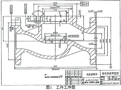
3) Draw the fourth chamfer of the machining diagram (see Figure 3). 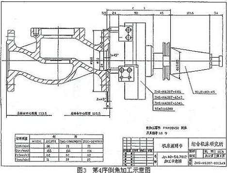
This sequence uses a special chamfering knife, and the position of the cutter head can be adjusted greatly. When processing a variety of different valve bodies, it can be adjusted according to the size of the machining icon (including the tip extension of the knife tip and the size of the tool tip to the center of the tool bar). Since this knife is used for many parts, the worker will adjust the knife according to this size. 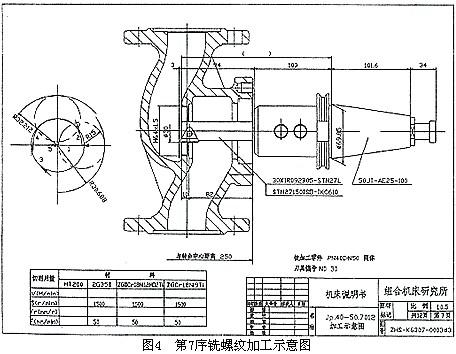
The above drawings have designed a total of 49 sets, each set of a set, each set of more than a dozen, a total of more than 700, by the user's factory operators praise. If the traditional method is used to design, it takes several times or even ten times to complete, and the quality of the drawings is relatively poor.
Example 2: A flexible production line plan designed for a factory in Chongqing.
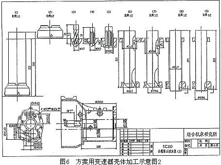
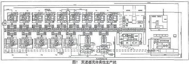
The plant requires the processing of six different transmission housings with a flexible production line. The production line consists of 14 vertical machining centers and 2 horizontal machining centers. Since most of the bidders are foreign manufacturers, the user's requirements for bidding are relatively high. It is required to draw a plan for each machine tool, each part, and each installation (see Figures 5-7). 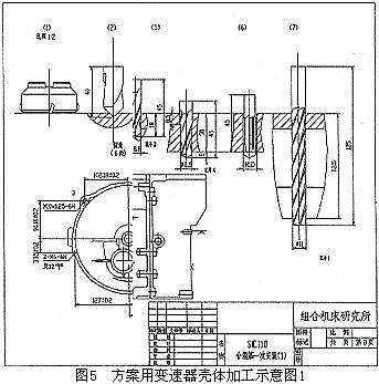
(m/min)
(mm/r)
(s)
(Making large noodles) 80 face milling cutter
=1.2 5
Carbide three-edged drill 8.8
8.8
Carbide three-edged drill 11 holes (two places)
15 holes
Auxiliary time (s)
Note: T = 82.5, T = 33, T = 20, T = 67.8.
T machine plus = 94.7, T total = 162.5.
Recently, we have also made an FMS solution for the processing of the reducer housing for an automobile factory, which is also well received by the user's factory.
The work we have done in this area is only a preliminary application. Most of the data, data and experience are accumulated in the actual work. The basic work is gradually carried out in practical applications. Further application remains to be seen. It can only be achieved after a lot of work. To this end, we must improve various databases, libraries, enrich the basic parts, develop various management software, call various modules according to different needs, and improve the automation of the design. The goal is to make full use of CAD technology in similar application projects, speed up design, improve design quality, and enhance competitiveness, so that we can gain a foothold in this field and be invincible.
Application of CAD in machining center and flexible design
Trojan`s new LCD touch screen programmable vacuum system for epoxy cold mounting, offers excellent pore impregnation in a compact format. This equipment can make epoxy resin penetrate into any porous samples quickly and effectively, resulting in ensured the edge protection of the sample. This equipment is light and compact, external connecting the compressed air source can quickly and effectively pulls a vacuum, and can also be connected to vacuum air pump.