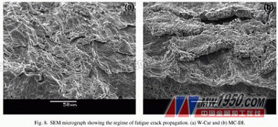
3.3 rupture orientation and surface observation F-Car and MC-DI fatigue crack propagation with zinc coatings indicates that interparticle ruptures work in concert with secondary cracks (figure a and b below). These SEM observations indicate that the low fatigue limit in galvanized W-Car and MC-DI tailored panels is the result of grain cracking. As discussed at the end of Sections 3 and 2, it is caused by the penetration of zinc into the surface of the steel sheet. This is consistent with the discovery that the surface conditions mentioned above are indeed one of the main factors affecting the fatigue life of materials. Previous page Laser Digital Detector for Guide Rail
Laser Digital
Detector for Straightness and Torsion Resistance of Elevator Guide Rail
Detector for
Elevator Guide Rail Geometric State
Laser Detector
for Elevator Guide Rail Coplanarity
Laser Corrector
for Elevator Guide Rail Installation
Laser Detector
for Elevator Guide Rail Verticality
Laser Detector
for Coplanarity of Distance Between Guide Rail
for OTIS Elevators, ThyssenKrupp Elevators, Schindler Elevators, KONE Elevators, Mitsubishi Elevators, Fujitec Elevators, Hitachi Elevators, Toshiba Elevators, Fuji Elevators, Express Elevators, Sigma Elevators, LG Elevators, Hyundai Elevators, BLT Elevators, CANNY Elevators, SJEC Elevators, KOYO Elevators
Laser Digital Detector for Guide Rail, Detector for Elevator Guide Rail, Laser Detector for Elevator Guide Rail, Laser Corrector for Elevator Guide Rail CEP Elevator Products ( China ) Co., Ltd. , https://www.zjfullelevatorreplacement.com
The rupture surface inspection indicates that different failure modes of the tailoring die are observed, and the initial fatigue cracks in all cases occur in the base metal. This is related to inclusions or porosity as shown in the figure below. For the W-Car and MC-DI compounds, the fatigue cracks in the thin base metal propagation were 0.75 and 0.80 mm, respectively. However, studies have found that the location of the failure of the thin base metal varies with the magnitude of the applied pressure. At low amplitudes of 90, 100, and 110 MPa, failure occurs approximately 2 mm from the weld beads; failure occurs at a high pressure amplitude of 120, 130 MPa, approximately 6-7 mm away from the weld beads. For GMX tailor-welded compound compounds, the failure occurs in a thin (0.9mm) base metal, which is approximately 6-7mm away from the solder beads over the entire application load range of 120-150 MPa. This phenomenon is due to the notch effect caused by the thickness variation of the tailored panel, so that the pressure is concentrated near the welding head. The difference in thickness of the base metal of the W-Car and MC-DI (0.92 and 1.2 mm) tailored panels is at least 1.5 times that of the GMX tailoring process. Therefore, the pressure concentration near the W-Car and MC-DI solder beads is stronger than that of the GMX. Other literature has reported similar results. Rhee et al. compared the geometry of different samples with parallel and perpendicular weld heads operating in the loading direction. The initial crack and final rupture of the sample loaded perpendicular to the weld bead occurred in the base metal similar to our current observation. This indicates that the impedance of the high-hardness solder beads as shown in Fig. 3 is higher than the impedance of the base metal. Oh et al. found that the notch effect caused by the discontinuous surface that caused the pressure concentration and the fatigue limit to decrease made the fatigue limit of the similar thickness of the welded panel higher than that of the dissimilar welding. Lazzarin et al also reported that their sample visual inspection under pressure did not reveal any significant lateral displacement of the solder beads. Lee et al. observed the fatigue failure of the smashed welded panels occurring in the heat sensitive zone and the failure of the laser trimming panel in the base metal. Compared to laser-welded panels, smashed welds have a stronger notch effect and therefore have lower fatigue strength at beating tensile pressure. 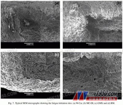
4. to sum up
1. Microstructural examination of the welded cross joints revealed that the weld was not affected by defects such as porosity, concavity, voids, inclusions or uncalibrated. This indicates that the welding parameters for the tailored panel are suitable and a good welding effect can be obtained.
2. The micro-hardness of the welded beads after laser welding is nearly 2.5 times that of the single base metal that makes up the tailored panel. These are all due to the formation of good pearlite and low carbon bainite structures in the weld metal, while the base metal is composed of equiaxed grain ferrite harpoon.
3. The fatigue limit of uncoated tailored panels has been found to be approximately 1.4 times that of galvanized tailored panels.
4. It has been observed that fatigue cracking always occurs on the steel sheet of the tailored panel. However, the location of the crack is related to the pressure concentration caused by the difference in thickness of the steel sheet. It has been observed that fatigue failure occurs near the weld bead in the case of large thickness differences, and failure always occurs away from the weld when the tailored panel has a small thickness difference.
5. The base metal and the cutting jig are mainly used to propagate fatigue cracks in the form of fatigue fringes, and the intergranular cracking of the galvanized cutting jigs is caused by the penetration of zinc below the surface of the steel sheet. This is also the reason why the fatigue limit of galvanized welded panels is lower than that of uncoated tailored panels.
We carry high quality Laser Digital Detector for Guide Rail for all major elevator and escalator brands