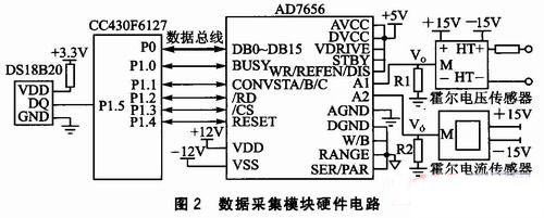
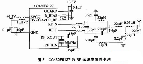
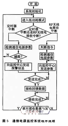
introduction As the scale of communication networks continues to expand, the number of communication power supplies continues to increase, and the monitoring of communication power supplies demonstrates its importance. The power of the communication base station is generally in a relatively dispersed state, and in most cases is unattended. In order to ensure real-time monitoring of communication power, it is extremely urgent to develop a system that can monitor communication power in real time. The communication power monitoring system is classified according to data transmission methods, including a monitoring system for telephone line communication, a monitoring system for GSM communication, and a monitoring system based on Web communication. The telephone line system requires a fixed line and has a high cost; GSM communication uses the short message channel to transmit data, and if the amount of data to be transmitted is relatively large, the cost is also high; the Web technology has relatively complete functions and superior performance, but based on Web communication. The monitoring system needs to lay network lines, and multiple Web sites are required for the case of more decentralized points, and the cost is also high. In view of the above shortcomings, the design scheme based on the combination of the Web and the single-chip CC430F6127 is adopted. The CC430F6127 integrates the CC1101 radio transceiver, which enables wireless transmission over a distance of 100 meters. Each RF radio communication module can act as a small repeater for indirect transmission, making the transmission distance farther. The RF radio module can be used to form a small-scale local area network, and then multiple small networks can be connected through a Web network to achieve the purpose of monitoring all communication power sources. This not only reduces the use of Web sites, but the low power consumption of the CC430F6127 makes the use cost lower and meets the requirements of the application. 1 Communication power monitoring system operation principle The main function of the communication power monitoring system is to monitor the power quality of the communication power supply and send the collected data to the monitoring center. The block diagram of the communication power monitoring system is shown in Figure 1. First, the communication power monitoring point will collect the energy data and calculate and analyze it. Then, the data is transmitted to the central point of the communication power monitoring sub-network through the RF radio communication channel, and the sub-network center point transmits all the monitored data to the monitoring center through the Web network, thereby realizing the purpose of monitoring all communication power sources. 2 system hardware design The hardware design of the communication power monitoring system is divided into the data acquisition module, the RF radio data transmission module and the CC430F6127 and the Web connection module of the monitoring system sub-network center point. The main task of the data acquisition module is to collect the power data of the communication power supply and perform related data analysis; the task of the RF radio module is to send the collected data to the central point of the communication power sub-network; the CC430F6127 and the Web connection module function to communicate The data collected by the central point of the power monitoring subnetwork is transmitted to the monitoring center through the web network. The following describes each module in detail. 2.1 Data Acquisition Module The data acquisition module needs to collect the voltage, current, temperature and other parameters of the communication power supply. The hardware circuit is shown in Figure 2. The data acquisition module is controlled by the single-chip CC430F6127 (referred to as F6127). First, the voltage and current of the communication power supply are converted by the Hall voltage sensor and the Hall current sensor respectively. The outputs of the two sensors are current signals, and the currents of the two sensors are respectively output. After the R1 and R2 sampling resistors, a voltage drop is formed across the resistor. Since one end of the resistor is grounded, the other end of the resistor, VO, is the converted voltage signal; then the voltage across the sampling resistors R1 and R2 is collected by the AD7656. The amplitude of the input voltage and current can be obtained according to the ratio of the sensor; F6127 can find the maximum and average values ​​of voltage and current through the relevant algorithm, and send this data to the monitoring center. The AD7656 analog-to-digital conversion chip used in this system is a 6-channel simultaneous sampling 16-bit successive approximation ADC, which can meet the requirements of high resolution, multi-channel, high slew rate and low power consumption. It is mainly used in power monitoring systems and instrument control systems. Wait. As shown in Figure 2, the power supply positive voltage VDD of the AD7656 is +12 V, the power supply negative voltage VSS is -12 V, and the analog voltage AVCC, logic voltage VDRIVE, and digital voltage DVCC are both +5V. STBY of AD7656 is connected to VDRIVE and selects normal mode; SER/PAR port is grounded and parallel interface is selected; W/B is grounded to indicate 16-bit parallel output; RANGE port is grounded to select input voltage range ±10V; WR/REFEN/DIS is connected to VDRIVE for selection Internal reference. The P0 port of the MCU F6127 is connected as the parallel data port to the parallel data ports DB0~DB15 of the AD7656. The P1.0 port is connected to the BUSY of the AD7656 to detect whether the conversion is over. The P1.1 port is connected to CONVST A, CONVST B and CONVST C. Three ports are connected to control the AD7656 to simultaneously sample six signals; the P1.2 port is connected to the read signal RD of the AD7656 as a read data control port; the P1.3 port is connected to the /CS end of the AD7656 as a chip select port; P1.4 The port is connected to the RESET port of the AD7656 as the restart control port. The communication power supply itself generates heat. Its temperature will affect the power supply performance of the power supply. Real-time measurement of the temperature of the communication power supply plays an important role in better controlling the power supply of the power supply. In this system, the DS18B20 temperature acquisition chip is used to collect the temperature of the communication power supply. The DS18B20 is a high-speed, high-precision temperature sensor with a power supply voltage of 3.3 V; the measurement range is -55 to +125 ° C; the measurement accuracy is 0.5 ° C. . When installing the temperature sensor, the DS18B20 chip needs to be as close as possible to the communication power supply. The P1.5 port of the MCU CC430F5137 is connected to the DQ port of the DS18B20 to control the read and write operations of the DS18B20. 2.2 RF radio data transmission module The RF radio data transmission device is composed of a CC1101 radio transceiver integrated in the CC430F6127 microcontroller. The CC430F6127 microcontroller is a combination of TI's MSP430F6xx series of MCUs and low-power RF transceivers. Extremely low current consumption in low power mode, battery-powered wireless networking applications can operate continuously for more than 10 years. The advanced features included in the micro package also provide the core power for an innovative RF sensor network that can report data to a central collection point. The CC430F6127 is a 16-bit ultra-low power: MCU with a maximum clock frequency of 20 MHz, 4 KB RAM, 32 KB Flash, 64 pins, CC1101 radio, supply voltage range of 1.8 to 3.6 V, current consumption in normal operating mode The current consumption of the LPM_3 is 160 μA/MHz, and the current consumption of the LPM_3 is 2.0 μA to PM_4. The RF frequency of the CC1101 radio transceiver integrated in the CC430F6127 microcontroller has three ranges: 300 to 348 MHz, 389 to 464 MHz, and 779 to 928 MHz. According to the data sheet provided by TI and the requirements of the system, the system's RF frequency is set to 433 MHz, the packet length can reach 20 bytes, the data transmission rate is 38.4 kbps, and the transmission power can reach 12.6 dBm. The system can adjust the transmission power according to the distance between the monitoring point and the monitoring center point of the sub-network to achieve the purpose of low power consumption. The hardware circuit is shown in Figure 3. The C CA30F6127 has a supply voltage of +3.3 V and an RF external crystal frequency of 26 MHz. RF_N and RF_P are the receive and transmit pins of the RF radio transceiver. Two-pin external electronics and power antenna. 2.3 Monitoring system sub-network center point C430F6127 and Web connection module CC430F6127 and Web connection adopts Crystal Semiconductor's network card chip CS8900A, which is a low-power Ethernet control chip. Its main internal functional modules include: serial EEPROM interface, ISA bus interface, cache RAM, Complete analog front-end 10BASE-T and AUI interface, IEEE 802.3-compliant Ethernet MAC engine. The CC43 0F6127 can directly control the CS8900A through the I/O port, as shown in Figure 4. CS8900A adopts 3.3V power supply voltage, adopts the default working mode, that is, 8-bit data bus for reading and writing. CC2.0F6127's P2.0~P2.3 ​​is connected with CS8900A's SA0~SA3 as address bus, SA8 and SA9 are connected to high level. SA4~SA7 and SA10~SA19 are grounded. The address is always 0300H when reset, P3.0~P3.7 of CC430F6127 is connected with SD0~SD7 of CS89 00A as the data line, and the remaining data lines of CS8900A are grounded, P4 of CC430F6127. The port 0 is connected to the port of the CS890 0A as a read control port, and the port P4.1 of the CC430F6127 is connected to the port of the CS8900A as a write control port. Two external LED indicators are convenient for observing the data transmission status. In order to protect the system security, the isolation transformer CL2246X is used in the middle of the CS8900A and RJ45 ports for isolation and isolation. 3 system software design The program flow of the communication power monitoring system is shown in Figure 5. First, the system is initialized, and the microcontroller CC430F6127 enters the low power mode. If the monitoring center sends a control command to the monitoring point, the CC430F6127 MCU of the monitoring point will generate an RF radio receiving interrupt. This interrupt will cause the MCU to wake up from the low-power mode and judge the control command sent by the monitoring center, and perform related operations, including current. , voltage, temperature measurement and other functions. These parameters are then sent to the monitoring center via the RF radio module. The communication power monitoring system not only needs to complete the function of detecting parameters, but also needs to monitor the power quality provided by the communication power source. Therefore, the system detects the power parameter of the communication power source after an interval of 5 s, and if the measured data exceeds the police line range, the alarm information is sent to the monitoring center. The monitoring center can also modify the interval of detection, alarm range and other parameters at any time. After the communication power monitoring point sends the data to the monitoring center through the RF radio, the monitoring center will resend the received data to the communication power monitoring point. After the monitoring point is received, it will check whether the sending data matches the received data. If they are the same, it means The transmission is successful. If it is not the same, the data is resent, which ensures the reliability of data transmission. 4 Conclusion This paper designs a communication power monitoring system based on Web and CC430F6127 microcontroller. The system has flexible networking and low power consumption, and can transmit the status of multiple communication power monitoring stations to the monitoring center in time for real-time analysis. The system runs stably and reliably, and has a great application prospect. [1]. CC1101 datasheet http:// We focused on international export product development, production and sales. We have improved quality control processes of Crystal Roller Shutter Door to ensure each export qualified product. Commercial Rolling Up Door,Roller Shutter Door for Shop,Crystal Roller Shutter Door,Commercial Roller Shutter Doors Shenzhen Hongfa Automatic Door Co., Ltd. , https://www.spiralfastdoor.com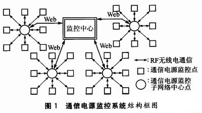

references:
[2]. AD7656 datasheet http://
[3]. DS18B20 datasheet http://
[4]. 2.0 datasheet http://
[5]. CS8900A datasheet http://
[6]. SA10 datasheet http://
If you want to know more about the products in Crystal Roller Shutter Door, please click the product details to view parameters, models, pictures, prices and other information about Crystal Roller Shutter Door.
Whatever you are a group or individual, we will do our best to provide you with accurate and comprehensive message about Crystal Roller Shutter Door!
Communication power supply monitoring system based on Web single chip and CC430F6127
0 times
Window._bd_share_config = { "common": { "bdSnsKey": {}, "bdText": "", "bdMini": "2", "bdMiniList": false, "bdPic": "", "bdStyle": " 0", "bdSize": "24" }, "share": {}, "image": { "viewList": ["qzone", "tsina", "tqq", "renren", "weixin"], "viewText": "Share to:", "viewSize": "16" }, "selectShare": { "bdContainerClass": null, "bdSelectMiniList": ["qzone", "tsina", "tqq", "renren" , "weixin"] } }; with (document) 0[(getElementsByTagName('head')[0] || body).appendChild(createElement('script')).src = 'http://bdimg.share. Baidu.com/static/api/js/share.js?v=89860593.js?cdnversion=' + ~(-new Date() / 36e5)];