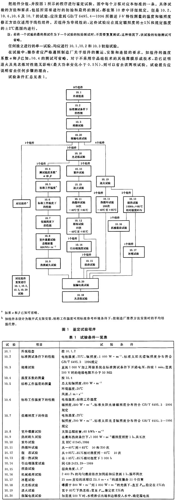
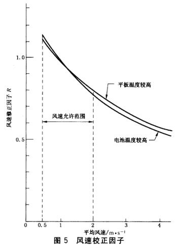
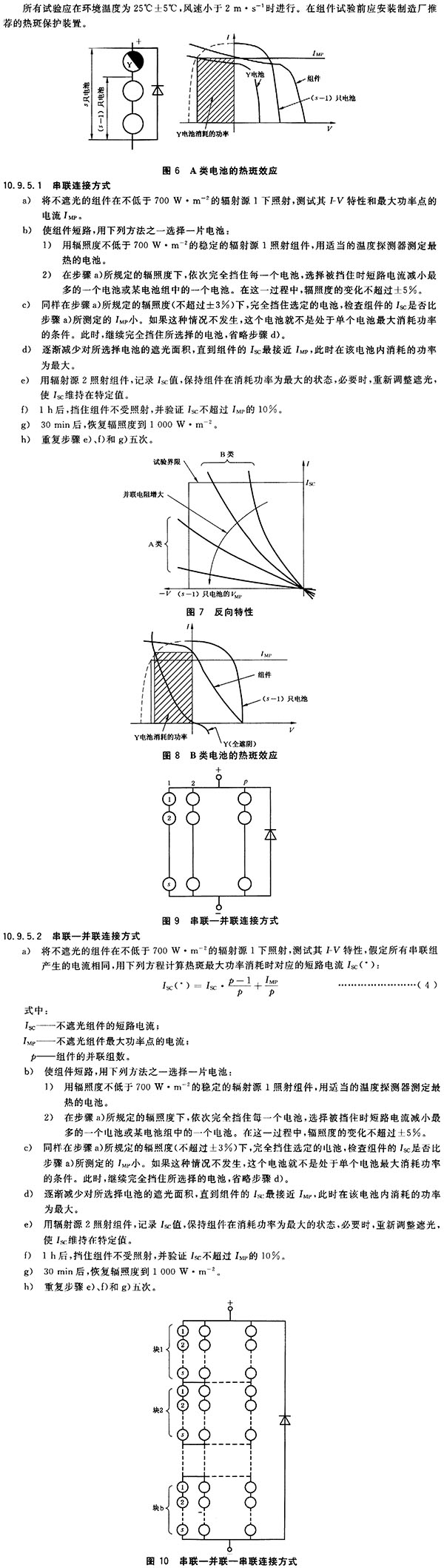
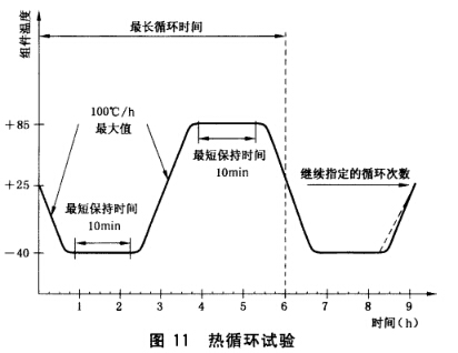
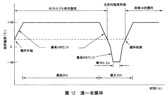
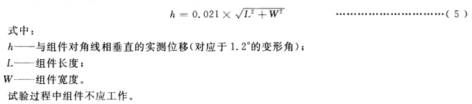
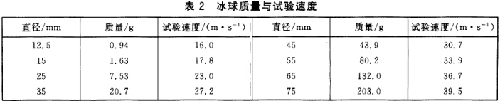
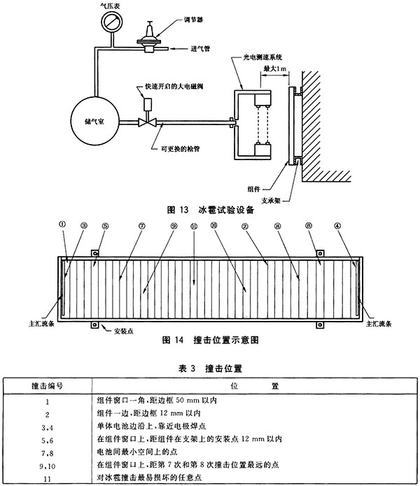
1 Scope and purpose This standard stipulates the requirements for the design, identification and finalization of thin film photovoltaic modules for use on the ground. The module is used under the general outdoor climate conditions defined in GB/T 4797.1-1984 and IEC 60721-2-1 Amendment 1:1987. . This standard was developed based on amorphous silicon thin-film module technology, but it is also applicable to other thin-film photovoltaic modules. Given the special properties of other new technologies, it may be necessary to make revisions to this test procedure. This test procedure is mainly based on GB/T 9535-1998 "Design and Identification of Crystalline Silicon Photovoltaic Modules for Ground Use" and makes some necessary modifications to the special properties of amorphous silicon thin film modules. Light aging is used to distinguish between photo-induced attenuation and other attenuation mechanisms, and the maximum power at the later stage of the test procedure is used as an estimate of the long-term performance of the membrane module. In order to distinguish the annealing effects that may occur during thermal cycling and wet-heat tests, components must be annealed before these tests. For other thin-film forming techniques that do not use amorphous silicon, pre-treatments such as light aging and annealing may be different or may prove unnecessary. Because all types of thin-film modules are prone to moisture-induced erosion, a wet-leakage current test must be added. The purpose of this test procedure is to determine the electrical and thermal properties of the module at the most reasonable possible cost and time, indicating that the module can be used for a long period of time under specified climatic conditions. The actual life expectancy of components passing this test will depend on the design of the components and the environment and conditions they use. This standard does not apply to components with a condenser. 2 normative references The clauses in the following documents have been adopted as references to this standard. For dated references, all subsequent amendments (not including errata content) or revisions do not apply to this standard, however, encourage the parties to reach an agreement based on this standard to study whether the latest version of these documents can be used . For undated references, the latest version is applicable to this standard. GB/T 2421-1999 Environmental testing for electric and electronic products - Part 1: General (idt IEC 60068-1:1988, Amendment 1 : 1992) GB/T 2423.3-1993 Basic Environmental Testing Procedures for Electrical and Electronic Products Test Ca: Constant Moist Heat Test Method (eqv IEC 60068-2-3:1984) GB/T 2423.29-1999 Environmental testing for electric and electronic products Part 2: Test methods Test U: Strength of terminals and integral mounts (idt IEC 60068-2-21:1992) GB/T 2829-2002 Periodic Inspection Count Sampling Procedures and Tables (Applicable to Inspection of Process Stability) GB/T 4797.1-1984 Electrotechnical products Natural environmental conditions Temperature and humidity (neq IEC 60721-2-1:1982) GB/T 6495.1-1996 Photovoltaic devices - Part 1: Measurement of photovoltaic current-voltage characteristics (idt IEC 60904-1:1987) GB/T 6495.3-1996 Photovoltaic devices - Part 3: Test principles and standard spectral irradiance data for ground-based photovoltaic devices (idt IEC 60904-3: 1989) GB/T 6495.4-1996 Temperature and irradiance correction methods for measured properties of crystalline silicon photovoltaic devices IV (idt IEC 60891:1987, 1st Amendment: 1992) GB/T 9535-1998 Design and qualification of crystalline silicon photovoltaic modules for ground use (eqv IEC 61215:1993) GB/T 2423.2-2001 Environmental testing for electric and electronic products Part 2: Test methods Test B: High temperature (idt IEC 60068-2-2: 1974, Amendment 1 : 1993, Amendment 2 : 1994) IEC 60721-2-1 Amendment 1: 1987 Classification of Environmental Conditions Part 2: Natural Environmental Conditions - Temperature and Humidity IEC 60904-9:1995 Photovoltaic devices - Part 9: Solar simulator performance requirements IEC 61345:1998 UV test of photovoltaic modules IECQC 001002: 1986 Amendment to the 2nd Amendment to the IECQ Rules for the Quality of Electronic Components (IECQ): 1994 3 sampling From the same batch or batches of products, eight (if needed to increase backup) components are randomly selected for the qualification test according to the method specified in GB/T 2829-2002. These components shall be manufactured from materials and components that comply with the relevant drawings and process requirements, and shall undergo routine inspection, quality control and product acceptance procedures by the manufacturer. The assembly should be complete, with manufacturer's instructions for handling, installation, and connection, including the system's maximum allowable voltage. If the component being tested is a newly designed sample rather than a production line, it should be stated in the test report (see Chapter 8). 4 mark Each component should have the following clear and indelible signs: a) the manufacturer's name, logo or code; b) product model; C) product serial number; d) polarity of the terminal or lead (marked by color code); e) the maximum system voltage allowed by the component; f) Nominal and minimum values ​​of the maximum output power of the model under standard test conditions. The date and place of manufacture should be indicated on the assembly or can be found by the product serial number. 5 test 6 Qualification Criteria If a test sample meets the following criteria, the component design is considered to have passed the qualification test and passed the finalization. a) Under standard test conditions, the maximum output power attenuation of the module does not exceed the specified limit after each single test; b) The maximum output power under standard test conditions after the final light aging is not less than 90% of the minimum value given by the manufacturer of Chapter 4; c) In the test process, no component shows an open circuit or leakage; d) No serious appearance defects as defined in Clause 7; e) Meet the test requirements of 10.3 and 10.20. If two or more components do not meet the above criteria, the design will be considered as not meeting the qualification requirements. If one component fails any of the tests, two other components satisfying the requirements of Clause 3 shall be tested from scratch for all relevant test procedures. If one or both of these components failed the test, the design was judged not to meet the qualification requirements. If both components pass the test, the design is considered to meet the qualification requirements. 7 serious appearance defects For design qualification and stereotypes, the following defects are serious appearance defects: a) broken, cracked, bent, irregular or damaged outer surface; b) Any thin film layer in the active working area of ​​the module has more than 10% of the area of ​​the cell, visible corrosion; c) the formation of a continuous bubble or delamination between the edge of the component and any part of the circuit; d) Loss of mechanical integrity, resulting in the installation and/or work of the components being affected. 8 Report After the approval of the type approval, the test agency shall provide the qualification test verification report according to the IECQC 001002:1986 Rules for the Quality Evaluation System of Electronic Components of the International Electrotechnical Commission. The certificate shall include the performance parameters of the test and the details of the failure, retest or omission test. . The manufacturer should keep a copy of the report for reference. 9 Re-qualification Any changes in the design, materials, components, or processes of the assembly may require the reassessment of some or all of the qualification tests to ensure the effectiveness of the product. 10 test procedures 10.1 appearance inspection 10.1.1 Purpose Check for any cosmetic defects in the assembly. 10.1.2 Procedures Under illumination of no less than 1000 lx, carefully inspect the following for each component: a) Cracked, curved, irregular or damaged outer surface; b) Defects in interconnection lines or joints; c) that any film layer in the active working area of ​​the module has voids and visible corrosion; d) visible corrosion of output connections, interconnection lines, and main bus lines; e) adhesive joint failure; f) There are sticky materials on the surface of plastic materials; g) Failure of the lead-out, exposed live parts; h) any other situation that may affect the performance of the component; i) Forming continuous channels of air bubbles or delaminations between the frame of the assembly and the battery. The status and location of any cracks, bubbles or delamination should be recorded and/or photographed. These defects may be exacerbated in subsequent tests and adversely affect the performance of the components. 10.1.3 Requirements For stereotypes, in addition to the serious appearance defects specified in Chapter 7, other appearance conditions are allowed. 10.2 Performance under Standard Test Conditions 10.2.1 Purpose Using natural light or class A simulator according to IEC 60904-9:1995 under standard test conditions (battery temperature: 25°C ± 2°C, irradiance: 1000W·M-2, standard solar spectrum irradiance distribution in accordance with GB / T 6495.1-1996 Provisions), Test the electrical performance of the assembly as a function of load. 10.2.2 Procedures According to the method of GB/T 6495.1-1996, the current-voltage characteristics of a component under standard test conditions are tested, and if necessary, the temperature and irradiance can be corrected according to the provisions of GB/T 6495.4-1996. 10.3 Insulation test 10.3.1 Purpose Measure the insulation between the current-carrying portion of the assembly and the assembly frame. 10.3.2 Test conditions The test conditions for the components: temperature is ambient temperature (see GB/T 2421-1999), relative humidity is not more than 75%. 10.3.3 Procedures a) Connect the positive terminal of the DC insulation tester to the current limiting device after short-circuiting the component leads. The current limit is set to 50μA. b) Connect the exposed metal part of the module to the negative electrode of the insulation tester. If the assembly has no bezel or the frame is a bad conductor, install the metal test stand for the assembly and connect it to the negative side of the insulation tester. c) Increase the voltage of the insulation tester at a rate of no more than 500V·s-1 until it equals 1000v plus twice the system maximum voltage (ie, the open circuit voltage of the system under standard test conditions). Maintain this voltage for 1min. If the system's maximum voltage does not exceed 50V, the applied voltage should be 500V. d) Without removing the component cable, reduce the voltage to zero and short-circuit the positive and negative terminals of the insulation tester for 5 minutes. e) Remove the short circuit between the positive and negative electrodes of the insulation tester. f) Connect the wires according to the steps a) and b), add a DC voltage of not less than 500V to the module, and measure the insulation resistance. 10.3.4 Test Requirements a) In 10.3.3 step c), there is no insulation breakdown (less than 50KA), or no surface cracking. b) The insulation resistance is not less than 50MΩ. 10.4 Temperature Coefficient Measurement 10.4.1 Purpose The current temperature coefficient (α) and voltage temperature coefficient (β) were measured from the component tests. The temperature coefficient so determined is only valid at the irradiance used in the test; for linear components, this is effective within ±30% of the irradiance. GB/T 6495.4-1996 stipulates that these coefficients are measured from single cells in a representative batch, and this method supplements this standard. The temperature coefficient of a thin-film battery assembly depends on the irradiation and the heat treatment process experienced by the assembly. When the temperature coefficient is involved, the conditions of the thermal test and the results of the irradiation should be indicated. 10.4.2 Devices a) Solar simulator (Class B or better) in accordance with IEC 60904-9:1995. Meet the GB/T 6495.1-1996 Chapter 2 measuring irradiance, short-circuit current and open circuit voltage equipment. Note: The pulsed solar simulator is preferred because it has a small amount of extra heat that affects the assembly during the evaluation process. If a steady-state solar simulator is used, a baffle or similar device should be installed so that the irradiation time is less than or equal to 55. b) The accuracy of the device measuring the surface of the module or the temperature of the battery is ±0.5°C. c) A laboratory capable of accommodating components, fitted with a transparent 1 and temperature adjustment device, capable of uniform heating and cooling within the required temperature range. 10.4.3 Procedures a) Measure the short-circuit current of the module by the method of GB/T 6495.1-1996 at room temperature and the required irradiance. b) Install the assembly in the laboratory and install an appropriate irradiance monitor outside the test room but still in the simulator lighting. Connect the instrument. c) Close the test chamber, set the irradiance, make the short circuit current of the test module reach the value of step a), and use the irradiance monitor to maintain the same level throughout the test. d) Heat the assembly to the highest temperature tested, turn off the heater and allow it to cool smoothly. e) Measure the short-circuit current and open-circuit voltage every 5°C during the component cooling process within a temperature range of at least 30°C. Note: Using the method of GB/T 6495.4-1996 Chapter 5 to determine the curve correction factor K, a complete current-voltage characteristic should be measured for each temperature. f) Draw the curves of Isc and Voc as a function of temperature, and fit a curve to the least squares method for each set of data. g) At the point between the highest and lowest temperature of interest, take the slope of the current and voltage curves and calculate the temperature coefficients α and β of the component. 10.5 The nominal operating temperature of the battery 10.5.1 Purpose Determine the nominal operating temperature (NOCT) of the component. 10.5.2 Introduction The nominal operating temperature is defined as the average equilibrium junction temperature of the solar cell under the following standard reference environment (SRE), open bracket installation: a) Inclination: At the midday sun in the local area, make the sun shine perpendicular to the components; b) Total irradiance: 800W·M-2; c) Ambient temperature: 20°C; d) Wind speed: 1m·s-1; e) Electrical load: Zero (open circuit). The system designer can use the nominal operating temperature as the reference temperature for the component to work in the field, so this parameter is a valuable parameter when comparing the performance of different component designs. However, the actual temperature of a component at any given time depends on the installation method, irradiance, wind speed, ambient temperature, sky temperature, reflected radiation and emitted radiation from the ground and surrounding objects. To accurately predict the performance of the component, the influence of the above factors should be taken into account. A description of the two methods for determining the nominal operating temperature: The first type is called "basic method" and can be used universally for all photovoltaic modules. When a component is not designed for open bracket installation, the basic method determines the equilibrium average solar cell junction temperature when installed in a standard reference environment using the method recommended by the manufacturer. The second type called "indirect method (reference plate method)" is faster than the first method, but can only be applied to the same environment as the reference plate used in the test (within a certain range of wind speed and irradiance). Temperature-responsive PV modules. Components with front and rear plastics fall into this category. Calibration of the reference plate uses the same procedure as the basic method. 10.5.3 Basic Method 10.5.3.1 Principle 10.5.3.2 Devices The following devices are required: a) Open brackets that support the component under test and the bolometer in a specific manner (see 10.5.3.3). The bracket should be designed to minimize thermal conduction to the assembly and interfere with the thermal radiation of the front and rear surfaces of the assembly as little as possible. Note: If components are not designed for open bracket installation, they should be installed in the manner recommended by the manufacturer. b) The radiation intensity meter is mounted on the plane of the assembly within 0.3 m from the test square. c) Equipment capable of measuring wind speed and wind direction up to 0.25 m·s-1, installed about 0.7m above the module, and 1.2m east or west. d) An ambient temperature sensor with a time constant similar to that of the module, installed in a well-shielded and well-ventilated place near the wind speed sensor. e) The battery temperature sensor, or other equipment approved by the national standard for measuring the temperature of the battery, shall be soldered or glued with good thermal conductivity to the back of the two batteries in the middle of each test assembly. 1) The data acquisition system records the following parameters at intervals not greater than 60 seconds: 1) Irradiance; 2) ambient temperature; 3) Battery temperature; 4) wind speed; 5) Wind direction; 6) Accuracy: The total accuracy of the nominal operating temperature is ±1K. 10.5.3.3 Installation of Test Components Inclination: Make the module irradiate the component vertically (±5°) in the local solar noon. Height: The bottom edge of the test assembly should be more than 0.6m above the local level or ground level. Arrangement: In order to simulate the thermal boundary conditions of the components mounted in a square array, the test assemblies should be mounted in a planar array extending at least 0.6 m in all directions of the test assembly plane. For arbitrarily fixed open-mounted components, the remaining surface of the planar array should be filled with black aluminum or other similarly designed components. Surrounding area: Within 4 hours before and after the local sun noon, there are no obstructions around the module and can receive sufficient solar radiation. The surrounding area of ​​the mounting assembly should be flat, or be tilted away from the test rack, and have no special high reflectivity to sunlight. It is permissible to have grass, other plants, black asphalt or dirt around the test site. 10.5.3.4 Procedure 10.5.4 Indirect Methods (Reference Plate Method) 10.5.4.1 Principle The principle of the method is to compare the temperature of the standard reference plate and the test assembly under the same irradiance, ambient temperature and wind speed conditions. The reference plate's steady-state temperature in a standard reference environment is determined by the basic method described in 10.5.3. First, the temperature difference between the test assembly and the reference plate is corrected to the standard reference environment, and this value is added to the average steady-state temperature of the reference plate under the standard reference environment, and the nominal operating temperature of the test assembly is obtained. Experiments have shown that temperature differences are insensitive to fluctuations in irradiance, ambient temperature, and small changes in wind speed. 10.5.4.2 Reference Tablet The reference plate is made of hard aluminum alloy. The dimensions are shown in figure 3. The front surface should be painted with matt black paint, and the back surface should be painted with bright white paint. There should be an instrument that meets the accuracy requirements to measure the temperature of the reference plate. The method of measuring with two sets of thermocouples is shown in Fig. 3. After removing the insulation material within 25mm from the junction of the thermocouple, the thermocouple is stuck in the groove carved with a good thermal insulation adhesive, and finally the two The remaining wires of the thermocouples were glued into a slot with aluminum powder putty. At least three reference plates should be prepared and calibrated using the basic method described in 10.5.3. The measured steady-state temperature should be in the range of 46 °C -50 °C, the difference between the three plate temperatures is not greater than 1 °C. A reference plate should not be used as a control reference. Prior to carrying out the nominal working temperature measurement, the steady-state temperature of the reference plate under the conditions specified in 10.5.3.4 c) shall be compared with the control plate to detect if there is a change in thermal performance between the two. If the measured plate temperature difference exceeds 1°C, the cause should be ascertained and corrected accordingly before testing the nominal operating temperature. 10.5.4.3 Test site Select a flat spot where the surrounding buildings, trees, and landforms barely interfere with the wind. Avoid uneven reflections of the ground or objects behind the test plate. 10.5.4.4 Devices The following devices are required (see Figure 4): a) The number of reference plates is specified in 10.5.4.2 (one more than the number of components tested simultaneously). b) A radiometer or standard solar cell. c) An open bracket that supports the test assembly, reference plate, and bolometer and directs them vertically (±5°) from sunlight at noon local time. The sides of each assembly are next to the reference plate, and the bottom edge of the assembly is approximately 1m above the ground. The stent should be designed to minimize thermal conduction to the assembly and the reference plate, and to minimize heat radiation from the front and rear surfaces of the assembly. d) Equipment capable of measuring wind speed and wind direction up to 0.25 m·s-1, mounted approximately 0.7m above the assembly and 1.2m to the east or west, as shown in Figure 4. e) An ambient temperature sensor with a time constant similar to that of the module, installed in a light-shielded, well-ventilated box near the wind speed sensor. f) The battery temperature sensor, or other equipment required by national standards to measure the temperature of the battery, shall be soldered or glued with good thermal conductivity to the back of the two batteries in the middle of each test assembly. 9) The data acquisition system records the following parameters at intervals not greater than 60 seconds: 1) Irradiance; 2) ambient temperature; 3) Battery temperature; 4) wind speed; 5) Wind direction; 6) reference plate temperature; 7) Accuracy: The total accuracy of the nominal operating temperature is ±1K. 10.5.4.5 Procedures 10.7 Performance at Low Irradiance 10.7.1 Purpose According to the provisions of GB/T 6495.1-1996, determine the natural light at 25°C and irradiance of 200W·m-2 (determined with appropriate standard equipment) or Class A simulator according to the requirements of IEC 60904-9:1995. The electrical performance of the component as a function of load. 10.7.2 Procedures According to GB/T 6495.1-1996, under the natural light at 25°C and irradiance of 200W·m-2 (determined with appropriate standard equipment) or Class A simulator according to IEC 60904-9:1995 requirements, the Current-voltage characteristics. Reduce the irradiance to a specific value with a neutral filter or other method that does not affect the spectral irradiance distribution. If necessary, correct for temperature and irradiance. 10.8 outdoor exposure test 10.8.1 Purpose The ability of the assembly to withstand exposure to outdoor conditions was initially evaluated to reveal the overall attenuation effect that may not be measured in laboratory tests. Note: Since the short-term and test conditions of the test vary with the environment, special care should be taken in determining the life of the module based on this test. This test can only be used as a guide to reveal possible problems or instructions. . 10.8.2 Loading a) Solar irradiance monitor with an accuracy of ±10%; b) Co-planar installation of the module with the irradiance monitor using the method recommended by the manufacturer for installation. 10.8.3 Procedures a) Open the module and install it outdoors in the manner recommended by the manufacturer, coplanar with the irradiance monitor. The hot spot protection equipment recommended by the manufacturer should be installed before the test. b) In general outdoor climate conditions as specified in Amendments 1987 to IEC 4777.1-1984 and IEC 60721-2-1, measured with a monitor, the total amount of radiation received by the module is 60 kWh·m-2. 10.8.4 Final Test Repeat the tests of 10.1, 10.2 and 10.3. 10.8.5 Requirements a) No serious appearance defects as specified in Chapter 7; b) The maximum output power under the standard test conditions shall be greater than the minimum rated value specified by the manufacturer; c) The insulation resistance shall meet the same requirements as the initial test. 10.9 Hot Spot Durability Test 10.9.1 Purpose Determine the ability of the component to withstand the hot spot heating effect, which may cause the package to degrade. Battery mismatch or cracks, failure of internal connections, partial shading or soiling can all cause this defect. 10.9.2 Hot Spot Effect When one cell or a group of cells in a module is shielded or damaged, the operating current exceeds the reduced short circuit current of the cell or battery, and hot spot heating occurs in the module. At this point, the affected battery or battery pack is placed in a reverse biased state, consuming power and causing overheating. FIG. 6 depicts the hot spot effect of a component made up of a series of series cells in which battery Y is partially shaded. The power consumed by Y is equal to the product of the component current and the reverse voltage formed across Y. For any irradiance level, the power consumed during a short circuit is the largest, The reverse voltage applied to Y is equal to the voltage generated by the remaining (s-1) cells in the assembly. The intersection of the inverse IV curve of Y and the mirror image of the forward IV curve of the (s-1) cell in Figure 6 Constitute a shaded rectangle to indicate the maximum power consumption. Since the reverse characteristics of different batteries vary greatly, it is necessary to divide the batteries into either voltage-limited (Type A) or current-limited (Type B) according to the intersection of their reverse characteristic with the “Test Limit Zone†shown in Figure 7. Two types. The situation of the maximum power consumption of the damaged or shading battery shown in FIG. 6 is Class A. This happens when the mirror image of the forward IV curve of the reverse curve and the (s-1) battery intersects at the maximum power point. By contrast, Figure 8 shows the maximum power consumption of a Class B battery when fully shielded. It should be noted that the power consumed at this time may only be part of the total effective power of the component. 10.9.3 Classification of Internal Battery Connections Solar cells in photovoltaic modules are connected in one of the following ways: Serial mode: a single battery is connected in series (Figure 6); Series-parallel connection mode: P groups will be connected in parallel, each group: a battery in series (Figure 9); A series-parallel connection-series connection mode: that is, b blocks in series, each block has p groups in parallel, each group, and each battery is connected in series (Figure 10). If there is a bypass diode, it is also considered to be part of the circuit under test because it limits the reverse voltage of the connected battery. Each type of structure requires a special hot spot test program. When the component is short-circuited, its internal power consumption is maximum. 10.9.4 Devices a) Radiation source I, a class C (or better) steady-state solar simulator or natural light in accordance with IEC 60904-9:1995, with an irradiance of not less than 700 W·m-2 and an unevenness of not more than ±2%, Instantaneous instability is within ±5%. b) Radiation source 2, a Class C (or better) steady-state solar simulator or natural light according to IEC 60904-9:1995, with an irradiance of 1000 W·m-2 and a deviation of ±10%. C) Component IV Curve Tester. d) A set of opaque cover plates with a 5% shading increase for the test solar cell. e) If necessary, add a suitable temperature detector. 10.9.5 Procedure 10.9.5.3 Series One Parallel One Series Connection Method a) Short-circuit the unshielded component and irradiate it under a stable radiation source 1 of not less than 700 W·m-2. Randomly take at least 30% of the individual cells in the assembly, blocking each cell in turn and measuring the stable temperature of the cell with a thermal imager or other suitable instrument. b> Fully shading the battery with the highest temperature found in step a). c) When continuously monitoring the battery temperature, gradually reduce the area of ​​light shielding the battery, and determine the conditions for the battery to reach the maximum temperature. d) Keeping the light blocking state at step c), irradiate the assembly with radiation source 2 . e) After 1h, block the components. f) After 30 minutes, restore the irradiance to 1000W·M-2. g) Repeat steps d), e) and f) five times. 10.9.6 Requirements a) No serious appearance defects as specified in Chapter 7; b) The insulation resistance shall meet the same requirements as the initial test; c) The attenuation of the maximum output power under standard test conditions does not exceed 5% of the test value before the test. 10.10 UV test 10.10.1 Purpose Determine the ability of the assembly to withstand ultraviolet (UV) radiation. UV tests are specified in IEC 61345:1998. If necessary, components should be light-aged before carrying out the test. 10.10.2 Requirements a) No serious appearance defects as specified in Chapter 7; b) The maximum output power under the standard test conditions shall be greater than the minimum rated value specified by the manufacturer; c) The insulation resistance shall meet the same requirements as the initial test. 10.11 Thermal cycling test 10.11.1 Purpose Determine the ability of the component to withstand thermal mismatches, fatigue, and other stresses caused by repeated changes in temperature. The assembly should be annealed as shown in Figure 1 before accepting the test. "Before the IV test" refers to the post-anneal test. Note that the components should not be exposed to light until the final IV test. 10.11.2 Devices a) Automatic temperature control test chamber, which allows internal air circulation and avoids moisture condensation on the surface of the assembly during the test, and can accommodate one or more components for the thermal cycling test as shown in FIG. b) There is a device for mounting or supporting the assembly in the test chamber and guarantee that the surrounding air can circulate freely. The heat conduction of the installation or support device should be small, so in fact, the assembly should be insulated. c) The instrument for measuring and recording the temperature of the module with an accuracy of ±1°C. The temperature sensor should be placed on the front or rear surface of the middle of the assembly. If multiple components are tested simultaneously, just monitor the temperature of one representative component. d) Instruments that monitor the electrical continuity of each component during the entire test. e) Instrument to monitor the insulation integrity between one lead and each frame or frame. 10.11.3 Procedures a) Pack the assembly in the test chamber at room temperature. If the frame of the assembly is not conductive, mount it on a metal frame to simulate an open support frame. b) Connect the temperature sensor to the temperature monitor and connect the two lead ends of the assembly to the electrical continuity tester: Connect one lead end of the assembly and the frame or support bracket to the insulation monitor. c) Close the test chamber so that the circulation rate of air around the unit is not less than 2m·s-1. As shown in Figure 1, the temperature of the unit will be cycled between -40°C±2°C and +85°C±2°C. The rate of temperature change between the maximum and minimum temperatures does not exceed 1000 C/h. At each extreme temperature, it should be stable for at least 10 minutes. The cycle time does not exceed 6 h. The number of cycles is shown in the corresponding box in Figure 1. d) Record the temperature of the module throughout the test and monitor any open circuit or leakage that may occur. 10.11.4 Final Test After a recovery time of at least 1 h, the tests of 10.1, 10.2 and 10.3 were repeated. 10.11.5 Requirements a) No interruption or leakage during the test; b) No serious appearance defects as specified in Chapter 7; c) The insulation resistance shall meet the same requirements as the initial test; d) The attenuation of the maximum output power under standard test conditions does not exceed 5% of the test value before the test. 10.12 Wet-frozen test 10.12.1 Purpose Determine the ability of the assembly to withstand high temperatures, high humidity, and subsequent subzero temperatures. This test is not a thermal shock test. Prior to accepting the test, the assembly should be annealed and subjected to a thermal cycling test as in FIG. "Before the IV test" refers to the test after thermal cycling, taking care not to expose the assembly to light before the final IV test. There are two methods to choose from: the single box method and the double box method. 10.12.2 One-box method 10.12.2.1 Devices a) A test chamber, with automatic temperature and humidity control, capable of accommodating one or more components for a wet-frozen cycle test as defined in FIG. At subzero temperatures, the dew point of the air in the chamber is the temperature of the chamber. b) Apparatus for measuring and recording the temperature of components, with an accuracy of ±1°C. If multiple components are tested simultaneously, just monitor the temperature of one representative component. c) Instruments that monitor the electrical continuity within each component throughout the test. d) Monitor the integrity of the well-insulated instrument between one lead and each frame or support. 10.12.2.2 Procedures a) Place the temperature sensor on the front or back surface of the middle of the assembly. b) Pack the assembly to the test chamber at room temperature so that its inclination to the horizontal plane is not less than 50° If the frame of the assembly does not conduct well, install it on a metal frame of a simulated open support frame. c) Connect the temperature sensor to the temperature monitor, connect the two lead ends of the assembly to the electrical continuity tester, and connect one of the lead ends of the assembly and the frame or support bracket to the insulation monitor. d) Close the test chamber and allow the assembly to complete 10 cycles as shown in FIG. The maximum and minimum temperatures shall be within +2°C of the set value, and the relative humidity shall be maintained within ± 5% of the set value at each temperature above room temperature. e) Record the temperature of the module throughout the test and monitor any open circuit or leakage that may occur during the test. 10.12.3 Two-box method 10.12.3.1 Devices a) The first chamber (test chamber A), with automatic temperature and humidity control, capable of heating one or more components from room temperature to 85°C at a relative humidity of 85%. b) A second chamber (test chamber B), with automatic temperature control, capable of cooling the module from room temperature to a temperature of 40°C. The dew point of the room is the same as the one-box method. c) The instrumentation requirements for temperature, internal electrical continuity and insulation integrity of the test assemblies are the same as the single box method. 10.12.3.2 Procedures a) Place the temperature sensor on the front or back surface of the middle of the assembly. b) Ensure that the air temperature in chambers A and B is room temperature and the relative humidity is 85% ± 5%. c) Place the assembly in the chamber A at room temperature so that its angle to the horizontal is not less than 5°. If the frame of the assembly is not conducting well, mount it on a metal frame of a simulated open support frame. d) Connect the temperature sensor to the temperature monitor, connect the two lead ends of the assembly to the electrical continuity tester, and connect one of the lead ends of the assembly and the frame or support bracket to the insulation monitor. e) The test chamber is closed and the assembly is subjected to the first part of one cycle as shown in Figure 12, warmed from room temperature and returned to room temperature. The maximum temperature should be within ±2°C of the set value. During this cycle, the relative humidity should be kept at 85%±5%. f) Move the components at room temperature as quickly as possible to the test box B, and install it in the same manner as mentioned above so that its inclination to the horizontal plane is not less than 50. Reconnect the temperature monitor, continuity tester and insulation monitor. . g) Closing the test chamber, subjecting the assembly to a second part of a cycle as shown in FIG. 12, cooling down from room temperature and again to room temperature. The minimum temperature should be within ±2°C of the set value. h) Repeat steps b) through g) and complete 10 cycles. During the entire test, record the temperature of the module and monitor any open circuit or leakage that may occur during the test. 10.12.4 Final Test After a recovery time of 2 h to 4 h, the tests of 10.1, 10.2, and 10.3 were repeated. 10.12.5 Requirements a) No interruption or leakage during the test; b) No serious appearance defects as specified in Chapter 7; c) The insulation resistance shall meet the same requirements as the initial test; d) The attenuation of the maximum output power under standard test conditions does not exceed 5% of the test value before the test. 10.13 Wet-heat test 10.13.1 Purpose Determine the ability of the assembly to withstand long-term moisture infiltration. 10.13.2 Procedures The test should be based on GB/T 2423.3-1993 and meet the following requirements: a) Pretreatment The assembly should be annealed before this test. "Before IV testing" means that the test should be performed after annealing. Note that the components should not be exposed to light before the final IV test. Place the components at room temperature in the test chamber. b) Severe conditions Test under the following harsh conditions: Test temperature: 85 °C ± 20C; Relative humidity: 85% ± 5%; Test time: 1000h. C) Recovery The component withstands a recovery period of 2h to 4h. 10.13.3 Final Test After the recovery period is over, repeat the tests of 10.1, 10.2 and 10.3. 10.13.4 Requirements a) No serious appearance defects as specified in Chapter 7; b) The insulation resistance shall meet the same requirements as the initial test; C) The maximum output power attenuation under standard test conditions does not exceed 5% before the test. 10.14 Terminal strength test 10.14.1 Purpose Determine whether the terminal and its attachment to the assembly can withstand the forces that are normally experienced during installation and operation. 10.14.2 Types of Terminals Consider two types of component leads: a) Type A: leads directly from the panel; b) Type B: lugs, wiring bolts, screws, etc.; C) Type C: Connector. 10.14.3 Procedures Pretreatment: 1 h measurement and test under standard atmospheric conditions. 10.14.3.1 Type A Outlet Tensile test: According to the method Ua of GB/T 2423.29-1999, the following conditions are met: a) All terminals should be tested; b) The tension should not exceed the weight of the assembly. Bend test: According to method Ub of GB/T 2423.29-1999, the following conditions are satisfied: a) All terminals should be tested; b) Perform 10 cycles using method 1 (each cycle is bent once in the opposite direction). 10.14.3.2 Type B Outlet Tensile and bending tests: a) The components exposed to the terminals shall be tested in the same way as the test for type A terminals, and all terminals shall be tested; b) If the terminal is enclosed in a protective box, the following procedure should be taken: 1) Cut the cable of the type and size recommended by the component manufacturer into the appropriate length, and connect it with the terminal in the box according to the recommended method. Use the provided cable clamp to carefully pass the cable through the hole in the gland. The lid should be firmly placed in place, and then tested according to the test method of type A lead-out. Torque test: According to the method Ud of GB/T 2423.29-1999, meet the following conditions: 2) All terminals should be tested; 3) Severity 1. In addition to the permanently fixed designated design, nuts and screws should be able to loosen. 10.14.3.3 Type C Outlet å°†ç»„ä»¶åˆ¶é€ åŽ‚æŽ¨èåž‹å·å’Œå°ºå¯¸çš„电缆切为åˆé€‚的长度与接æ’件线盒输出端相接,然åŽæŒ‰ä¸ŽA型引出端相åŒçš„试验方法进行试验。 10.14.4最åŽè¯•éªŒ é‡å¤è¯•éªŒ10.1å’Œ10.2。 10.14.5è¦æ±‚ â€”â€”æ— æœºæ¢°æŸå迹象; â€”â€”åœ¨æ ‡å‡†æµ‹è¯•æ¡ä»¶ä¸‹ï¼Œæœ€å¤§è¾“出功率的衰å‡ä¸è¶…过试验å‰æµ‹è¯•å€¼çš„5%。 10.15æ‰æ›²è¯•éªŒ 10.15.1目的 检查组件安装于éžç†æƒ³ç»“构上å¯èƒ½é€ æˆçš„éšæ‚£ã€‚ 10.15.2ç¨‹åº a)装备好组件以便于试验过程ä¸è¿žç»ç›‘测其内部电路的电连ç»æ€§åŠç»ç¼˜ç”µé˜»ã€‚ç»ç¼˜ç”µé˜»è¯•éªŒæ³•å¦‚10.3所述,æ¤æ—¶åªè¦ç»„件æŸä¸€å¼•å‡ºç«¯ä¸Žç»ç¼˜æµ‹è¯•ä»ªç›¸è¿žã€‚ b)ä¿æŒç»„件的三个角在åŒä¸€å¹³é¢ä¸Šã€‚ c)自上述平é¢ï¼Œç§»åŠ¨ç¬¬å››ä¸ªè§’如下è·ç¦»ï¼š 10.15.3最åŽè¯•éªŒ é‡å¤è¯•éªŒ10.1å’Œ10.2。 10.15.4è¦æ±‚ a)在试验过程ä¸æ— é—´æ‡æ–路或æ¼ç”µçŽ°è±¡ï¼› b)æ— ç¬¬7ç« ä¸è§„定的严é‡å¤–观缺陷; cï¼‰æ ‡å‡†æµ‹è¯•æ¡ä»¶ä¸‹æœ€å¤§è¾“出功率的衰å‡ä¸è¶…过åˆå§‹æµ‹è¯•å€¼çš„5%. 10.16机械载è·è¯•éªŒ 10.16.1目的 确定组件ç»å—风ã€é›ªæˆ–覆冰ç‰é™æ€è½½è·çš„能力。 10.16.2ç¨‹åº a)装备好组件以便于试验过程ä¸è¿žç»ç›‘测其内部电路的电连ç»æ€§ã€‚ b)ç”¨åˆ¶é€ åŽ‚æ‰€è¿°çš„æ–¹æ³•å°†ç»„ä»¶å®‰è£…äºŽä¸€åšå›ºæ”¯æž¶ä¸Šï¼ˆå¦‚æžœæœ‰å‡ ç§æ–¹æ³•ï¼Œé‡‡ç”¨å›ºå®šæ€§æœ€å·®çš„一ç§æ–¹å¼ï¼Œå³å…¶å›ºå®šç‚¹é—´è·ç¦»æ˜¯æœ€å¤§çš„)。 c)在å‰è¡¨é¢ä¸Šï¼Œé€æ¥å‡åŒ€åœ°å°†è´Ÿè·åŠ 到2400Pa(è´Ÿè·å¯é‡‡ç”¨æ°”åŠ¨åŠ åŽ‹ï¼Œæˆ–å……æ°´çš„è¢‹å覆盖在整个表é¢ä¸Šï¼Œå¯¹äºŽåŽä¸€ç§æƒ…况,组件应水平放置),ä¿æŒæ¤è´Ÿè·1h。 d)将组件ä»ç½®äºŽåŒä¸€æ”¯æž¶ä¸Šï¼Œåœ¨èƒŒé¢é‡å¤ä¸Šè¿°æ¥éª¤ã€‚ e)é‡å¤æ¥éª¤c)å’Œæ¥éª¤d). 阵风安全系数为3时,2400Pa对应于130km·h-1风速的压力(约±800Pa)。若è¦è¯•éªŒç»„件承å—冰和雪é‡åŽ‹çš„能力,则试验过程ä¸ï¼ŒåŠ 于组件å‰è¡¨é¢çš„è´Ÿè·åº”从2400P。增至5400Pa。 10.16.3最åŽè¯•éªŒ é‡å¤10.1,10.2å’Œ10.3的试验。 10.16.4è¦æ±‚ a)在试验过程ä¸æ— é—´æ‡æ–路或æ¼ç”µçŽ°è±¡ï¼› b)æ— ç¬¬7ç« ä¸è§„定的严é‡å¤–观缺陷; c)ç»ç¼˜ç”µé˜»åº”满足åˆå§‹è¯•éªŒçš„åŒæ ·è¦æ±‚ï¼› d)æ ‡å‡†æµ‹è¯•æ¡ä»¶ä¸‹æœ€å¤§è¾“出功率的衰å‡ä¸è¶…过åˆå§‹æµ‹è¯•å€¼çš„5%。 10.17冰渔试验 10.17.1目的 验è¯ç»„件能ç»å—ä½å†°é›¹çš„撞击。 10.17.2装里 a)用于浇铸所需尺寸冰çƒçš„åˆé€‚ææ–™çš„æ¨¡å…·ã€‚æ ‡å‡†ç›´å¾„ä¸º25mm,对特殊环境å¯ç”¨è¡¨2所列其他尺寸。 b)一å°ä½Žæ¸©ç®±ï¼ŒæŽ§åˆ¶åœ¨-10℃±5℃范围内。 c)一å°æ¸©åº¦åœ¨-4℃±2℃范围内的储å˜å†°çƒçš„å˜å‚¨å®¹å™¨ã€‚ d)一å°å‘射器,驱动冰çƒä»¥æ‰€é™å®šé€Ÿåº¦ï¼ˆå¯åœ¨Â±5%范围内)撞击在组件指定的ä½ç½®èŒƒå›´å†…。åªè¦æ»¡è¶³è¯•éªŒè¦æ±‚,冰çƒä»Žå‘射器到组件的路径å¯ä»¥æ˜¯æ°´å¹³ã€ç«–直或其他角度。 e)一åšå›ºæ”¯æž¶ä»¥æ”¯æ’‘è¯•éªŒç»„ä»¶ï¼ŒæŒ‰åˆ¶é€ åŽ‚æ‰€æ述的方法安装,使碰撞表é¢ä¸Žæ‰€å‘射冰çƒçš„路径相垂直。 f)一å°å¤©å¹³æ¥æµ‹å®šå†°çƒè´¨é‡ï¼Œå‡†ç¡®åº¦ä¸ºÂ±2%。 9)一å°æµ‹é‡å†°çƒé€Ÿåº¦çš„设备,准确度为12%ï¼Œé€Ÿåº¦ä¼ æ„Ÿå™¨è·è¯•éªŒç»„件表é¢1m以内。 作为一个例å,图13示出一组适åˆçš„装置,包括:水平气动å‘射器ã€åž‚直支承组件的安装和测速器(用电å技术测é‡å†°çƒç©¿è¿‡ä¸¤å…‰æŸé—´è·ç¦»æ‰€ç”¨æ—¶é—´æ¥æµ‹é‡å…¶é€Ÿåº¦ï¼‰ã€‚ 10.17.3ç¨‹åº a)利用模具和低温箱制备足够试验所需尺寸的冰çƒï¼ŒåŒ…括åˆè°ƒå‘射器所需数é‡ã€‚ b)检查æ¯ä¸ªå†°çƒçš„尺寸ã€è´¨é‡åŠæ˜¯å¦ç¢Žè£‚,å¯ç”¨å†°çƒåº”满足如下è¦æ±‚: 1)肉眼看ä¸åˆ°è£‚纹; 2)直径在è¦æ±‚值±5%范围内; 3)质é‡åœ¨è¡¨2ä¸ç›¸åº”æ ‡ç§°å€¼Â±5%范围内。 c)使用å‰ï¼Œç½®å†°çƒäºŽå‚¨å˜å®¹å™¨ä¸è‡³å°‘1h。 d)ç¡®ä¿æ‰€æœ‰ä¸Žå†°çƒæŽ¥è§¦çš„å‘射器表é¢æ¸©åº¦å‡æŽ¥è¿‘室温。 e)用下述æ¥éª¤9)的方法对模拟é¶è¯•éªŒå‘å°„å‡ æ¬¡ï¼Œè°ƒèŠ‚å‘射器,使å‰è¿°ä½ç½®ä¸Šçš„é€Ÿåº¦ä¼ æ„Ÿå™¨æ‰€æµ‹å®šçš„å†°çƒé€Ÿåº¦åœ¨è¡¨2ä¸å†°é›¹ç›¸åº”试验速度的±5%范围内。 f)室温下安装组件于å‰è¿°çš„支架上,使其碰撞é¢ä¸Žå†°çƒçš„路径相垂直。 g)将冰çƒä»Žå‚¨å˜å®¹å™¨å†…å–出放人å‘射器ä¸ï¼Œçž„准表3指定的第一个撞击ä½ç½®å¹¶å‘射。冰çƒä»Žå®¹å™¨å†…移出到撞击在组件上的时间间隔ä¸åº”超过60s。 h)æ£€æŸ¥ç»„ä»¶çš„ç¢°æ’žåŒºåŸŸï¼Œæ ‡å‡ºæŸå情况,记录下所有看得è§çš„撞击影å“。与指定ä½ç½®å差应ä¸å¤§äºŽ10mm。 i)如果组件未æŸå,则对表3ä¸å…¶ä»–撞击ä½ç½®é‡å¤æ¥éª¤b)和h),如图14所示。 10.17.4最åŽè¯•éªŒ é‡å¤10.1,10.2å’Œ10.3的试验。 10,17.5è¦æ±‚ aï¼‰æ— ç¬¬7ç« ä¸è§„定的严é‡å¤–观缺陷; b)ç»ç¼˜ç”µé˜»åº”满足åˆå§‹è¯•éªŒçš„åŒæ ·è¦æ±‚ï¼› c)æ ‡å‡†æµ‹è¯•æ¡ä»¶ä¸‹æœ€å¤§è¾“出功率的衰å‡ä¸è¶…过åˆå§‹æµ‹è¯•å€¼çš„5%。 10.18å…‰è€ç‚¼è¯•éªŒ 10.18.1目的 通过模拟太阳è¾å°„的方法,稳定薄膜组件的电性能。 10.18.2装置 a)符åˆIEC 60904-9:1995çš„C类太阳模拟器。 b)å¸¦ç§¯åˆ†å™¨çš„æ ‡å‡†è£…ç½®ï¼Œä»¥ç›‘æµ‹è¾å°„é‡ã€‚ cï¼‰ç”¨åˆ¶é€ åŽ‚æŽ¨èçš„å®‰è£…æ–¹æ³•å®‰è£…ç»„ä»¶ï¼Œä¸Žæ ‡å‡†è£…ç½®å…±å¹³é¢å®‰è£…。 d)两åªå‡†ç¡®åº¦ä¸ºÂ±0.5℃的çƒç”µå¶è¿žæŽ¥åˆ°æ¯ä¸ªç»„件背é¢ï¼Œä¸€åªæŽ¥äºŽä¸éƒ¨ï¼Œå¦ä¸€åªæŽ¥äºŽè¾¹ç¼˜ï¼Œåº”ç¡®ä¿è¿žæŽ¥å…·æœ‰è‰¯å¥½çš„导çƒæ€§èƒ½ã€‚ e)ä¿æŒç»„件温度在确定温度±2℃以内的装置,该温度由两åªçƒç”µå¶çš„å¹³å‡æ¸©åº¦ç¡®å®šã€‚ 10.18.3ç¨‹åº a)ä½¿ç»„ä»¶å¼€è·¯ï¼Œç”¨åˆ¶é€ åŽ‚æŽ¨èçš„æ–¹æ³•å°†å…¶ä¸Žæ ‡å‡†å™¨ä»¶å®‰è£…åœ¨æ¨¡æ‹Ÿå™¨æµ‹è¯•å¹³é¢ä¸Šã€‚ b)å°†è¾ç…§åº¦è®¾ç½®åœ¨800W·m-2å’Œ1000W·m-2é—´ï¼Œç”¨æ ‡å‡†è£…ç½®è®°å½•è¾ç…§åº¦ã€‚ c)确认组件温度在40℃-50℃范围内,其温度å˜åŒ–å°äºŽÂ±2℃,记录温度。 d)è¾ç…§å„组件,直到最大功率值在连ç»äºŒä¸ªä»¥ä¸Šæ—¶æ®µï¼ˆæ¯ä¸ªæ—¶æ®µè‡³å°‘48h)çš„å˜åŒ–在2%以内。 进行最大功率值的测é‡æ—¶ï¼Œç»„件的温度å¯æ ¹æ®è¯•éªŒæ–¹ä¾¿é€‰å–,但å„次间的å˜åŒ–应在±2℃。 e)记录达到稳定时的è¾å°„é‡ã€‚ 10.18.4最åŽè¯•éªŒ é‡å¤10.1,10.2åŠ10.3的试验。 10.18.5è¦æ±‚ a)æ— ç¬¬7ç« ä¸è§„定的严é‡å¤–观缺陷; b)ç»ç¼˜ç”µé˜»åº”满足åˆå§‹è¯•éªŒçš„åŒæ ·è¦æ±‚。 c)最终的光è€ç‚¼ä¹‹åŽï¼Œæ ‡å‡†æµ‹è¯•æ¡ä»¶ä¸‹çš„最大输出功率应ä¸ä½ŽäºŽç¬¬4ç« æ‰€è¿°åˆ¶é€ åŽ‚è§„å®šçš„æœ€å°å€¼çš„90%。 10.18.6试验报告 下列试验æ¡ä»¶åŠç»“果应报告: a)试验期间的平å‡è¾ç…§åº¦ï¼› b)试验结æŸæ—¶çš„è¾å°„é‡ï¼› c)试验期间组件的温度; d)试验å‰åŽç»„件的最大功率。 10.19退ç«è¯•éªŒ 10.19.1目的 在鉴定试验å‰ï¼Œå°†è–„膜组件退ç«ã€‚如ä¸é€€ç«ï¼Œåœ¨åŽç»ç¨‹åºè¯•éªŒè¿‡ç¨‹ä¸çš„åŠ çƒå¯èƒ½æŽ©ç›–å…¶ä»–åŽŸå› å¼•èµ·çš„è¡°å‡ã€‚ 10.19.2装置 å¯ä¿æŒ85℃±2℃试验温度的高温室。 10.19.3ç¨‹åº è¯•éªŒåº”éµå¾ªIEC 60068-2-2:1988规定的试验Ba或Bbã€å¹²çƒè¯•éªŒï¼Œå¹¶æ»¡è¶³ä»¥ä¸‹æ¡ä»¶ï¼š a)é¢„å¤„ç† å®¤æ¸©ä¸‹çš„ç»„ä»¶æœªç»é¢„处ç†æ”¾äººé«˜æ¸©å®¤å†…。 b)严酷æ¡ä»¶ 1)试验温度:85℃±2℃ 2)试验周期:退ç«å¤„ç†å„组件,直到最大功率值在连ç»ä¸‰ä¸ªä»¥ä¸Šæ—¶æ®µï¼ˆæ¯ä¸ªæ—¶æ®µè‡³å°‘20h)çš„å˜åŒ–在2%以内。进行最大功率值的测é‡æ—¶ï¼Œç»„件的温度å¯æ ¹æ®è¯•éªŒæ–¹ä¾¿é€‰å–,但å„次间的å˜åŒ–应在±2℃。 c)æ¢å¤ 组件应ç»è¿‡è¶³å¤Ÿæ¢å¤æ—¶é—´ï¼Œä½¿å…¶æ¸©åº¦ç¨³å®šè‡³å®¤æ¸©ã€‚ 10.19.4最åŽè¯•éªŒ é‡å¤10.1,10.2åŠ10.3的试验。 10.19.5è¦æ±‚ a)æ— ç¬¬7ç« ä¸è§„定的严é‡å¤–观缺陷; b)ç»ç¼˜ç”µé˜»åº”满足åˆå§‹è¯•éªŒçš„åŒæ ·è¦æ±‚ï¼› cï¼‰æ ‡å‡†æµ‹è¯•æ¡ä»¶ä¸‹çš„最大输出功率应ä¸ä½ŽäºŽç¬¬4ç« æ‰€è¿°åˆ¶é€ åŽ‚è§„å®šçš„æœ€å°å€¼ã€‚ 10.19.6试验报告 下列试验æ¡ä»¶åŠç»“果应报告: a)退ç«æ—¶é—´ï¼› b)试验å‰åŽç»„件的最大输出功率。 10.20湿æ¼ç”µæµè¯•éªŒ 10.20.1目的 评价组件在潮湿工作æ¡ä»¶ä¸‹çš„ç»ç¼˜æ€§èƒ½ï¼ŒéªŒè¯é›¨ã€é›¾ã€éœ²æ°´æˆ–溶雪的湿气ä¸èƒ½è¿›äººç»„件内部电路的工作部分,如果湿气进人到该处å¯èƒ½ä¼šå¼•èµ·è…蚀ã€æ¼ç”µæˆ–安全事故。 该试验å¯é‡‡ç”¨ä¸¤ç§æ–¹æ³•ï¼š a)边缘浸泡法; b)淹没法。 10.20.2装置 a)盛有符åˆä»¥ä¸‹è¦æ±‚的水或溶液的槽或容器: 电阻率:ä¸å¤§äºŽ35000Ω·cmï¼› 表é¢å¼ 力:ä¸å¤§äºŽ3N·M-2ï¼› 温度:22℃±3℃。 )边缘浸泡法:容器应足够大,溶液应足够深,以ä¾æ¬¡æµ¸æ³¡ç»„件的æ¯ä¸ªè¾¹ç¼˜ï¼Œæº¶æ¶²é¢åº”高于组件芯æ¿ä¸Žè¾¹æ¡†çš„结åˆå¤„。容器应有安全支撑组件的装置。 2)淹没法:容器尺寸应å¯ä»¥å°†ç»„件水平放置于溶液内,溶液深度应完全覆盖所有表é¢ï¼ˆé™¤ä¸é€‚宜浸泡的接线盒人å£ä¹‹å¤–)。 b)盛有相åŒæº¶æ¶²çš„喷淋装置。 c)能é™æµçš„500Vç›´æµç”µæºã€‚ d)测é‡æ¼ç”µæµçš„装置。 e)如果组件没有导电边框,则需一个导电网ã€é‡‘属薄片或支架。 10.20.3程åºä¸€è¾¹ç¼˜æµ¸æ³¡æ³• 所有连接必须代表推èçš„å„ç§çŽ°åœºå®‰è£…接线方å¼ï¼Œå¹¶å°å¿ƒç¡®ä¿è¿žæŽ¥äºŽç»„件的仪器设备ä¸äº§ç”Ÿæ¼ç”µæµã€‚ a)如需è¦ï¼Œä½¿ç»„件的外表é¢å‡è¿žæŽ¥å¯¼ç”µç½‘ã€é‡‘属薄片或支架。 b)在容器内浸泡组件æŸä¸€è¾¹ç¼˜30s,ä¸è¦æ³¡åˆ°å¼•å‡ºç«¯æˆ–引线盒。用喷淋装置,彻底浇湿引线盒åŠå¼•çº¿å¼•å‡ºç‚¹ã€‚在整个30s的浸泡时间内,连ç»å–·æ·‹ä»¥ä¿æŒè¯¥æ¹¿æ¶¦çŠ¶æ€ã€‚ c)将组件输出端çŸè·¯ï¼Œè¿žæŽ¥åˆ°æµ‹è¯•è®¾å¤‡çš„æ£æžï¼Œå°†ç»„件的任何暴露的金属部分ã€å¯¼ç”µè¾¹æ¡†ã€å¯¼ç”µç½‘ã€é‡‘属薄片或支架接地,并连接到测试设备的负æžã€‚ d)以ä¸è¶…过500V·s-1çš„é€Ÿåº¦å¢žåŠ æµ‹è¯•è®¾å¤‡æ‰€æ–½åŠ çš„ç”µåŽ‹ç›´åˆ°500V,ä¿æŒè¯¥ç”µåŽ‹2min,测试æ¼ç”µæµã€‚ e)å‡ä½Žç”µåŽ‹åˆ°é›¶ï¼Œå°†æµ‹è¯•è®¾å¤‡çš„引出端çŸè·¯2min,åŒæ—¶ä¿æŒä¸Žç»„件的所有连接。 f)对该组件的其他边缘é‡å¤æ¥éª¤b)到e)。 10.20.4程åºä¸€æ·¹æ²¡æ³• 所有连接应代表推è现场安装接线情况,并å°å¿ƒç¡®ä¿è¿žæŽ¥äºŽç»„件的仪器设备ä¸äº§ç”Ÿæ¼ç”µæµã€‚ a)在盛有è¦æ±‚溶液的容器内淹没组件,其深度应有效覆盖所有表é¢ï¼Œä¸è¦æ³¡åˆ°æ²¡æœ‰ä¸ºæµ¸æ³¡è€Œè®¾è®¡çš„引线盒人å£ã€‚引线人å£åº”用溶液彻底喷淋。 b)将组件输出端çŸè·¯ï¼Œè¿žæŽ¥åˆ°æµ‹è¯•è®¾å¤‡çš„æ£æžï¼Œä½¿ç”¨é€‚当的金属导体将测试液体连接到测试设备的负æžã€‚ c)以ä¸è¶…过500V·s-1çš„é€Ÿåº¦å¢žåŠ æµ‹è¯•è®¾å¤‡æ‰€æ–½åŠ çš„ç”µåŽ‹ç›´åˆ°500V,ä¿æŒè¯¥ç”µåŽ‹2min,测试æ¼ç”µæµã€‚ d)å‡ä½Žç”µåŽ‹åˆ°é›¶ï¼Œå°†æµ‹è¯•è®¾å¤‡çš„引出端çŸè·¯2min,åŒæ—¶ä¿æŒä¸Žç»„件的所有连接。 10.20.5è¦æ±‚ a)在执行æ¥éª¤10.20.3d)å’Œ10.20.4c)过程ä¸ï¼Œæ²¡æœ‰ä»‹è´¨å‡»ç©¿æˆ–表é¢å¼€è£‚。 b)æ¼ç”µæµå°äºŽ10μA,æ¯å¢žåŠ 1m2组件é¢ç§¯å¯å¢žåŠ 5μA。对于边缘浸泡法,所有边缘测得的æ¼ç”µæµçš„总和ä¸åº”超出该è¦æ±‚。 Exhaust Valve,Exhaust Cutout Valve,Exhaust Valve Control,Egr Valves LIANGGONG VALVE GROUP CO.,LTD , https://www.lgvalvegroup.com