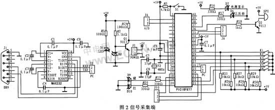
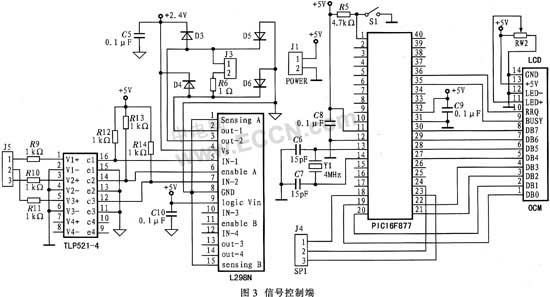
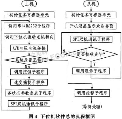
DC motor monitoring system is an important part of electromechanical products, and its control performance reflects the control quality of electromechanical equipment. Flexible, convenient, accurate, and real-time monitoring requires measurement and processing of the motor's speed signal to achieve precise control of the speed. 2 overall system design Although ARM/DSP/FPGA has high precision and high speed, the design is complicated and the price has always been high. This system uses a powerful RTOS-Salvo for small-capacity memory microcontrollers (such as PIC series). There is no need to expand a large amount of RAM and ROM, and the real-time performance is good. Significant cost savings. The system selects PC as the upper computer, and uses API function and MSCOMM control to realize computer communication. The PIC16F877A microcontroller and peripheral circuits form a single-chip microcomputer system. As a lower computer. The circuit design includes PWM drive, CCP capture, A/D analog-to-digital conversion, LCD liquid crystal display, RS232 and SPI serial communication, and the lower computer two-machine communication module. The overall block diagram of the system is shown in Figure 1. 3 Salvo System Introduction The embedded real-time operating system Salvo has two characteristics of occupying less system resources and powerful functions. 3.1 System resources occupied by Salvo The biggest feature of Salvo is that it takes up less system resources, especially the memory resources are very small. It is not only suitable for 51 series MCUs, but also for PIC series MCUs with less memory resources. Salvo occupies ROM resources depending on the system functions called by the user. RAM usage depends on the number of user-defined variables, tasks, and events. Taking the PIC16 series MCU as an example, each global variable occupies 10 B, the task occupies 5 B, and the event occupies 3 B. 3.2 Salvo function and performance Salvo is a task-driven multitasking embedded real-time operating system based on priority task switching. Salvo supports a total of 16 task priorities, and multiple tasks can share one priority. Tasks are switched by priority. For multiple tasks of the same priority, they are switched in round-robin mode. The number of tasks and events that Salvo supports depends on the size of the RAM (Salvo supports 255 tasks, 255 events, and 255 message queues by default). The Salvo kernel mainly provides the following types of functions for user application references: Task management: provide task creation and task cancellation functions; Time management: Provide task delay function function; Signal management: provide functions such as semaphore establishment, deletion, waiting, and sending; Message Management: Provides functions such as message creation, deletion, waiting, and sending. 4 System Hardware Overview The communication part is mainly composed of two parts: communication between the single chip computer and the PC and the PIC single chip. The data transmitted between the PC and the lower MCU adopts RS232 serial asynchronous communication. The communication between PIC microcontrollers uses the SPI bus, which is a 4-wire interface mainly used for synchronous serial communication between processors and peripherals. The serial clock is used to shift the serial data into and out of the microcontroller in the form of an 8-bit code. The SPI bus is a master/slave interface that drives the serial clock. When using SPI, it will send and receive data at the same time, making it a full-duplex protocol, with high communication efficiency, and simple circuit connection and software programming structure. The hardware circuit is shown in Figure 2 and Figure 3. The unit circuit includes CCP capture circuit, PWM drive circuit, RS232/SPI communication module, A/D conversion algorithm and LCD display. 4.1 CCP capture circuit In the photoelectric acquisition module, the photoelectric device has high conversion precision, good static working point, complete analog front end and on-chip calibration, and is especially suitable for measuring low frequency small signals. The circuit converts the optical signal into a voltage signal, which can be directly sent to the microcontroller after shaping and filtering. The speed signal sent to the microcontroller can be measured by the CCP capture module. In this mode, to use the capture function, set the corresponding TRIS to 1, and set the CCPx pin of the microcontroller as an input. For example, when the input frequency is stable, the MCU prescaler value is set to 1:16, and the total error of these 16 cycles is 1 TCY. Its effective resolution is TCY/16, which is an effective resolution of 6.25 ns at 40 MHz. This method is only effective if the input frequency is stable for 16 sample periods. When the prescaler (1:1) is not used, each sample resolution is TCY. Also, when the capture mode is changed, a capture interrupt is generated. The user should keep the CCPxIE bit clear to disable this interrupt and clear the CCPxIF bit after the Run mode is changed. The entire capture process is quick and easy. 4.2 PWM driver module The PWM signal generated by the PIC16F877A microcontroller is connected to the enable control terminal of the L298N through a photocoupler. Considering that the TLP521-4 circuit has an inverter function, the high level duration in the PWM signal corresponds to the power down time of the DC motor. The signal output from other pins of the MCU is sent to the direction control terminal of L298N to control the rotation direction and braking state of the DC motor. The power supply voltage of the L298N drive load is up to 46 V. The drive power of the single bridge is close to 2A, and the maximum switching frequency is not less than 40 kHz. Compared with a bridge drive circuit composed of discrete components, the circuit has a simple structure and reliable performance. By rewriting the program, you can control multiple shifts of small DC motors. Using a photoelectric encoder to achieve motor speed detection constitutes a complete closed-loop control system. 4.3 RS232 serial communication module The PIC16F877A serial port only occupies the RC6 and RC7 pins of the microcontroller and is used for the receive RXD and the transmit TXD. Therefore, when the upper computer and the lower computer communicate with each other, it is only necessary to connect the transmission and reception signals (TX, RX) and the ground (GND) to three lines. The serial interface level of the microcontroller is TTL level, which is inconsistent with the serial interface level of the computer, so level shifting is required. The system uses Maxim's MAX232 universal serial receive/transmit driver, which has a simple peripheral circuit and requires only four external 0.1μF capacitors. 4.4 LCD display module The module SMC1602B consists of a dot matrix LCD screen and controller HD44780 and its auxiliary circuits. The system design uses OCMJ Chinese module system LCD liquid crystal as the display module of the lower position machine. The module contains GB2312 16×16 dot matrix national standard simplified Chinese characters and ASCII 8×8 (half height) and 8×16 (full height) dot matrix English fonts. The user can input the location code or ASCII code to realize text display. OCMJ Chinese LCD module adopts ASK/ANSWER handshake mode. 5 System Software Overview 5.1 lower computer software design The software design of the lower computer of the intelligent motor monitoring system mainly completes many functions such as CCP capture, A/D acquisition, PWM control, SPI communication, LCD display, RS232 communication and so on. The overall flow block diagram is shown in Figure 4. The control algorithm uses the PIC16F877A to directly control the PID parameters for precise control. 5.2 PC system design The host computer system software is developed on the Windows platform using Vi-sual Basic 6.0, and the design includes the operation prompt part (automatic sending, manual sending, serial port selection, parity, baud rate, data bit, etc.), receiving back. The display part (receive data bit, motor speed, motor forward and reverse, etc.) and the content of the transmission (motor speed setting, overvoltage, overcurrent protection value, etc.). 6 Monitoring When the motor is working, the upper and lower position machines communicate in real time, and the displayed parameter values ​​are in real time. At this time, the motor is in the reverse state (forward rotation "1", reverse "0"), this aspect can be from the upper computer interface. On the other hand, the positive and negative setting flag shows that there is also a motor forward/reverse sign in the parameter of the lower machine feedback. The liquid crystal panel of the lower computer also has the speed, voltage, current and positive and negative display (forward "Right" , "Left" is reversed, and the data display of the upper and lower computers is synchronized. At the same time, the overcurrent and overvoltage protection value set by the host computer to the lower computer can be used to send an alarm signal when the circuit detects any overcurrent or overvoltage (over the set value). The red light is on, the buzzer sounds, the error message appears on the upper computer, the error message on the LCD of the lower computer, etc.), and the automatic shutdown protection, waiting for maintenance. 7 Conclusion The system successfully realizes the real-time monitoring of the closed-loop speed system of the DC motor, simplifies the control logic system, and has lower cost, complete function and good anti-interference performance compared with similar products. It has been successfully applied to DC motor speed regulation, monitoring and protection, and the host computer has a friendly interface and is easy to use. The PC can perform real-time monitoring of the DC motor, which not only greatly improves the stability during high-speed operation, but also realizes the protection function.
Hydraulic Piston Pump, Duplex Pump, Short-Stroke Pump, Noise/Vibration Reduction, High Self-Priming Ability, Rotational Stability, High Efficiency, High Pressure, Compact Size, Reduction of Overall Length.
Kubota hydraulic pumps provide low-noise, high efficiency and high reliability with various controls for construction machinery.
We export GENUINE PUMP, OEM PUMP, AFTERMARKET PUMP. We are specialized in OEM PUMP & AFTERMARKET PUMP. We export 95 NATIONS. Please contact us If you need STABLE SUPPLIER.
Kubota Hydraulic Main Pump,Kubota Main Hydraulic Pump,Kubota Hydraulic Pump,Kubota Hydraulic Pump Spare Parts,Kubota Hydraulic Main Pump Assembly,Kubota Main Pump,Kubota Pump,Kubota Hydraulic Parts,Kubota Excavator Parts Jining Juheng Hydraulic Machinery Co., Ltd. , https://www.sdjuhengmachine.com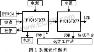
:
Realization of DC motor monitoring closed-loop speed system
1 Introduction
1 time
Window._bd_share_config = { "common": { "bdSnsKey": {}, "bdText": "", "bdMini": "2", "bdMiniList": false, "bdPic": "", "bdStyle": " 0", "bdSize": "24" }, "share": {}, "image": { "viewList": ["qzone", "tsina", "tqq", "renren", "weixin"], "viewText": "Share to:", "viewSize": "16" }, "selectShare": { "bdContainerClass": null, "bdSelectMiniList": ["qzone", "tsina", "tqq", "renren" , "weixin"] } }; with (document) 0[(getElementsByTagName('head')[0] || body).appendChild(createElement('script')).src = 'http://bdimg.share. Baidu.com/static/api/js/share.js?v=89860593.js?cdnversion=' + ~(-new Date() / 36e5)];