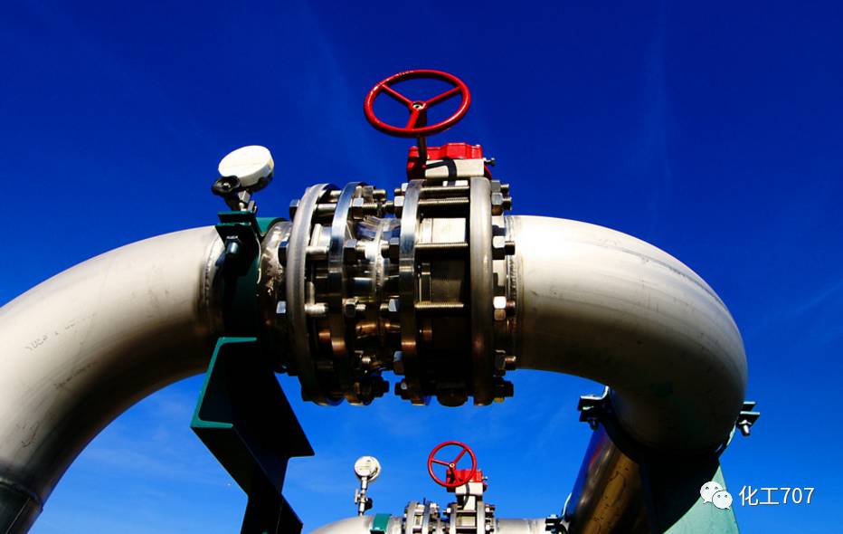
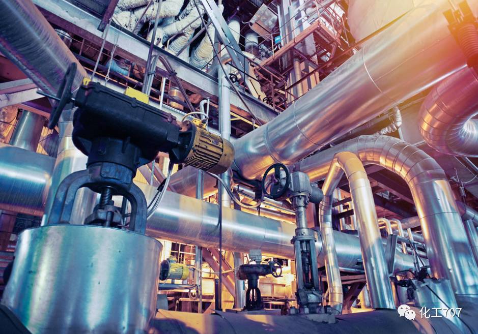
In the piping system, the valve is the control element, just like the human hand, so its importance is self-evident, both in life and in all walks of life. What are its functions? how to install? What does the common logo mean? How to repair if there is a malfunction? The most important four aspects, next, let's get to know! 4 functions 1. Cut-off and open media The flow channel is a straight-through valve with a small flow resistance and is typically selected as a valve for cut-off and open media. Down-closed valves (stop valves, plunger valves) are less preferred because of their meandering flow path and higher flow resistance than other valves. Where a higher flow resistance is allowed, a closed valve can be used. Control flow Valves that are easy to adjust flow are usually selected for control flow. Closed down valves (e.g., valve) is adapted to this purpose, because it is proportional to the relationship between the stroke of the valve closure member dimensions. Rotary valves (plug valves, butterfly valves, ball valves) and flexing valve body valves (clamping valves, diaphragm valves) can also be used for throttling control, but are usually only available in a limited range of valve sizes. The gate valve is a cross-cut movement of the circular valve seat with a disc-shaped shutter. It can control the flow better only when it is close to the closed position, so it is usually not used for flow control. This valve can have three or more passages depending on the need for a commutation split. Plug valves and ball valves are more suitable for this purpose, so most of the valves used for commutating splits select one of these valves. However, in some cases, other types of valves can be used for commutation splitting by simply connecting two or more valves to each other. 4. Medium with suspended particles When the medium has suspended particles, it is most suitable to use a valve with a wiping action of the sliding member along the sealing surface. 3 major installation issues 1. Pre-installation inspection 1. Check carefully that the valve type and specifications meet the drawing requirements. 2. Check the valve stem and disc opening for flexibility, jamming and skewing. 3. Check the valve for damage and whether the threaded valve thread is positive and intact. 4. Check that the combination of the valve seat and the valve body is firm, the valve disc and the valve seat, the valve cover and the valve body, and the valve stem and the valve flap are coupled. 5. Check that the valve gasket, packing and fasteners (bolts) are suitable for the properties of the working medium. 6. The old or long-lasting pressure reducing valve should be disassembled, and dust, sand and other debris must be cleaned with water. 7. Clear the port cover, check the degree of sealing, and the valve flap must be closed tightly. 2. General provisions for installation 1. The position of the valve installation should not hinder the operation, disassembly and maintenance of the equipment, the pipeline and the valve body itself, and the aesthetic appearance of the assembly should be taken into consideration. 2. The valve on the horizontal pipe, the valve stem is installed upwards, or installed at a certain angle, and the hand wheel cannot be installed downward. The valves, stems and handwheels on the high-altitude pipeline can be installed horizontally, and the valve is opened and closed remotely with a chain that is vertically lower. 3. Arranged symmetrical, neat and beautiful; the valve on the riser, under the premise of the process, the valve hand wheel is the most suitable for the chest height, generally 1.0€€1.2m from the ground, and the valve stem must be operated Install in the direction. 4. The valves on the side-by-side pipes shall have the same centerline elevation and the clearance between the handwheels shall not be less than 100mm; the valves on the side-by-side horizontal pipes shall be staggered to reduce the pipe spacing. 5. When installing heavier valves on pumps, heat exchangers, etc., valve brackets should be provided; when operating frequently and installed on valves more than 1.8m from the operating surface, a fixed operating platform should be provided. 6. The valve body has an arrow mark on the valve body, and the direction of the arrow is the flow direction of the medium. When installing the valve, care should be taken to point the arrow at the same direction as the media in the pipe. 7. When installing the flange valve, ensure that the end faces of the two flanges are parallel and concentric with each other. Do not use double gaskets. 8. When installing a threaded valve, a threaded valve should be equipped with a union for ease of disassembly. The setting of the joint should consider the convenience of maintenance. Usually, the water flow passes through the valve and then passes through the joint. Three. Installation precautions 1. The valve body material of the valve is mostly made of cast iron, which is brittle and therefore must not be hit by heavy objects. 2. When carrying the valve, it is not allowed to throw it at hand; when lifting and lifting the valve, the rope should be attached to the valve body, and it is strictly prohibited to lie on the hand wheel, the valve stem and the flange bolt hole. 3. The valve should be installed in the most convenient place for operation, maintenance and overhaul. It is strictly prohibited to be buried underground. The valves on the pipes directly buried and in the trench shall be inspected to facilitate the opening and closing and adjustment of the valves. 4. The thread should be intact and wrapped around the thread, leaded with lead oil or wrapped with Teflon tape. When turning the buckle, use a wrench to catch the hexagonal valve body screwed into one end of the pipe. 5. When installing the flange valve, pay attention to tighten the connecting bolt in the diagonal direction. When the screwing is used, the force should be even to prevent the gasket from being deflected or causing deformation and damage of the valve body. 6. The valve should remain closed during installation. For threaded valves that are closer to the wall, it is often necessary to remove the stem valve disc and handwheel to complete the installation. When disassembling, the handwheel should be turned to keep the valve open, and then disassembled. Installation of 6 common pipeline valves Gate valve Also known as the gate valve, the valve is used to control the opening and closing of the valve, and the flow rate of the pipeline is adjusted and the pipeline is opened and closed by changing the cross section. Gate valves are mostly used for pipes that are fully or fully closed to fluid media. Gate valve installation is generally non-directional, but cannot be flipped. 2. Globe valve It is a valve that uses a valve flap to control opening and closing. The medium flow or the medium path is cut by changing the gap between the valve flap and the valve seat, ie changing the cross-section of the passage. The flow of the fluid must be observed when installing the shut-off valve. The principle that must be observed when installing the shut-off valve is that the fluid in the pipeline passes through the valve hole from bottom to top, commonly known as “low-in and high-outâ€, and is not allowed to be reversed. Check valve, also known as check valve and check valve, is a valve that automatically opens and closes under the pressure difference between the front and the back of the valve. Its function is to make the medium flow only in one direction, and prevent the medium from flowing backwards. The check valve has a lift type, a swing type and a butterfly clip type according to its structure. The lift check valve is divided into horizontal and vertical. When installing the check valve, attention should also be paid to the flow direction of the medium, which cannot be reversed. Pressure reducing valve The pressure reducing valve is a valve that adjusts the inlet pressure to a certain required outlet pressure and relies on the energy of the medium itself to automatically maintain the outlet pressure. From the point of view of fluid mechanics, the pressure reducing valve is a throttling element whose local resistance can be changed, that is, by changing the throttling area, the flow velocity and the kinetic energy of the fluid are changed, resulting in different pressure loss, thereby achieving the purpose of decompression. Then, relying on the adjustment of the control and regulation system, the fluctuation of the post-valve pressure is balanced with the spring force, so that the post-valve pressure remains constant within a certain error range. installation 1. The vertically installed pressure reducing valve group is generally placed along the wall at a suitable height from the ground; the horizontally installed pressure reducing valve group is generally installed on a permanent operating platform. 2. The applied steel is loaded into the wall outside the two control valves (usually used for the shut-off valve) to form the bracket, and the bypass pipe is also stuck on the bracket to level the alignment. 3. The pressure reducing valve should be installed upright on the horizontal pipe, and should not be inclined. The arrow on the valve body should point to the flow direction of the medium and should not be reversed. 4. Both sides should be equipped with a shut-off valve and high and low pressure gauges to observe the pressure changes before and after the valve. The diameter of the pipe after the pressure reducing valve should be larger than the diameter of the inlet pipe before the valve 2#-3#, and the bypass pipe is installed for maintenance. 5. The pressure equalizing pipe of the membrane type pressure reducing valve should be connected to the low pressure pipe. For low pressure pipelines, safety valves should be provided to ensure safe operation of the system. 6. When used for steam decompression, set the drain pipe. For piping systems that require a high degree of purification, a filter is placed in front of the pressure reducing valve. 7. After the installation of the pressure reducing valve group, pressure reducing valve and safety valve should be pressure tested, flushed and adjusted according to the design requirements, and the adjusted mark should be made. 8. When flushing the pressure reducing valve, close the pressure reducing valve inlet valve and open the flushing valve for flushing. V. Traps The basic function of the steam trap is to discharge the condensate, air and carbon dioxide gas in the steam system as quickly as possible; at the same time, to minimize the automatic leakage of steam. There are many types of traps, each with different properties. According to the working principle of the trap, it can be converted into the following three types: €€ Mechanical type: Acting on the change of the liquid level of the condensate in the steam trap include: Float type: The float is a closed hollow sphere. Open-up float type: The float is a barrel type with an open upward. Open down float type: The float is a bucket type with an open downward. €€ thermostatic type: action based on changes in liquid temperature include: Bimetal: The sensitive component is a bimetal. Steam pressure type: The sensitive component is a bellows or ink cartridge, and the inside is filled with volatile liquid. €€ Thermal type: Acting on changes in the thermodynamic properties of the liquid. include: Disc type: Due to the different flow rates of liquid and gas under the same pressure, the different dynamic and static pressures generated drive the disc valve. Pulse type: When condensed water of different temperatures passes through the two-pole series orifice plate, different pressures are formed between the two-pole orifice plate to drive the valve flap to move. installation 1. A shut-off valve (stop valve) shall be provided before and after. A filter shall be provided between the trap and the front shut-off valve to prevent dirt in the condensed water from clogging the trap. 2. An inspection tube should be set between the trap and the rear shut-off valve to check whether the trap is working normally. If the inspection tube is opened for a large amount of steam, the trap is broken and needs to be repaired. 3. The bypass pipe is provided to discharge a large amount of condensed water at the time of starting, and to reduce the displacement load of the steam trap. 4. When the trap is used to remove the condensate from the heat equipment, it should be installed in the lower part of the heat equipment, so that the water pipe is returned vertically to the steam trap to prevent water from being stored in the heat equipment. 5. The installation location should be as close as possible to the drainage point. If the distance is too far, air or steam will accumulate in the elongated pipe in front of the trap. 6. Hydrophobic issues should be considered when the steam mains pipeline is too long. Safety valve The safety valve is a special valve in which the opening and closing member is in a normally closed state under the action of an external force. When the pressure of the medium in the equipment or the pipeline rises above a specified value, the medium is prevented from exceeding the specified value by discharging the medium outside the system. . Safety valves are automatic valves, mainly used in boilers, pressure vessels and pipelines. The control pressure does not exceed the specified value, which plays an important role in protecting personal safety and equipment operation. Note The safety valve must be pressure tested before it can be used. installation 1. The product must be carefully inspected before installation to verify whether there is a certificate of conformity and product specifications to clarify the pressure at the factory. 2. Safety valves should be placed as close as possible to the platform for inspection and maintenance. 3. The safety valve should be installed vertically, so that the medium should flow out from the bottom to the top and check the verticality of the stem. 4. Under normal circumstances, the shut-off valve cannot be installed before and after the safety valve to ensure safety and reliability. 5. Safety valve pressure relief: When the medium is liquid, it is generally discharged into the pipeline or closed system; when the medium is gas, it is generally discharged to the outdoor atmosphere. 6. Oil and gas medium can generally be exhausted to the atmosphere. The outlet of the safety valve venting pipe should be 3m higher than the highest structure around it, but the following conditions should be arranged in a closed system to ensure safety. 7. The diameter of the population pipeline should be at least equal to the inlet diameter of the valve; the diameter of the discharge pipe should not be smaller than the diameter of the outlet of the valve. The discharge pipe should be led to the outside and installed with a bent pipe so that the pipe outlet faces the safety zone. 8. When the safety valve is installed, when the connection between the safety valve and the equipment and piping is open-hole welding, the diameter of the opening should be the same as the nominal diameter of the safety valve. 61 kinds of identification symbols commonly used in the installation process (click on the image to view) Common faults and causes (click on the image to view) General pipeline valve 1. Reasons for the leakage of the stuffing box and maintenance methods 2. Valve stem failure reasons and maintenance methods 3. Sealing surface leakage causes and maintenance methods 4. Other faults, causes and maintenance methods [Automatic Pipe Valve] 1. Check valve common faults, causes, prevention and repair 2. Traps, common faults, causes, prevention and repair 3. Common faults, causes, prevention and maintenance of pressure reducing valves 4. Safety valve common faults, causes, prevention and repair Solar Fan,solar electric fan,solar energy fan,outdoor solar fan JIANGMEN ESCLIGHTING TECHNOLOGY LIMITED , https://www.jmwindfansummer.com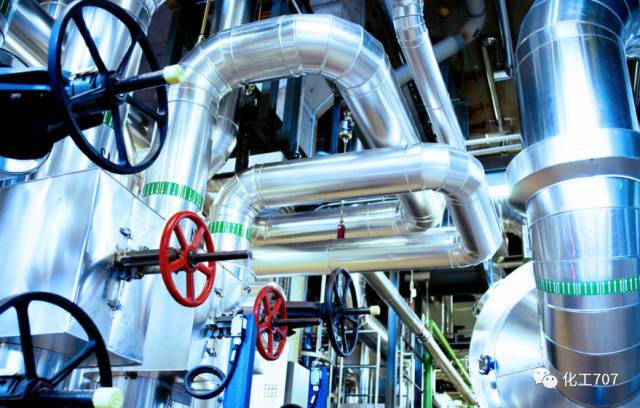
Three. commutating diversion
If the closing movement of the closure to the valve seat is vertical, the particles may be held, so that the valve is only suitable for substantially clean media unless the sealing surface material allows for the incorporation of particles. The ball valve and the plug valve have a wiping action on the sealing surface during the opening and closing process, so it is suitable for use in a medium with suspended particles. 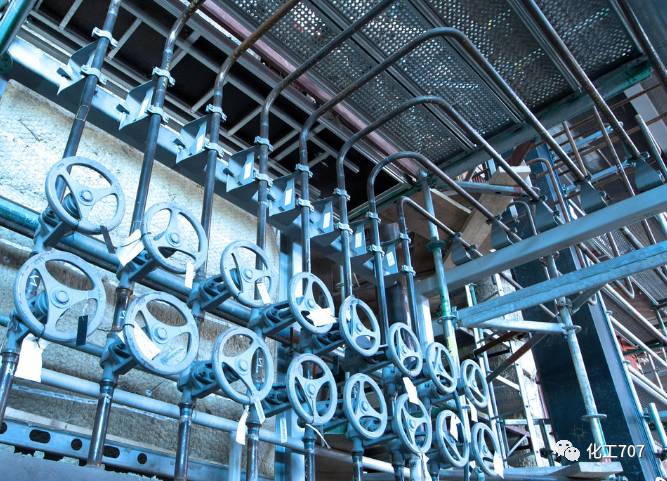
Three. Check valve 


