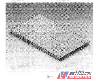
2. Insert a new series of parts design table If you have Microsoft Excel installed on your computer, you can use SolidWorks to automatically generate a series of part design tables that you can use to embed a new series of parts design tables directly in the part file. By applying the values ​​in the table to the dimensions of the part, the series design table allows you to create a number of different configurations for the part. The specific steps are as follows: (1) Open the built scale body part model with SolidWorks (2) Insert the "-" series part design table in the middle hit toolbar, under the source, the middle hit automatically generates ", and then click OK" in the pop-up size dialog box, select the dimension parameters related to the structure in the sketch and features. Join, click "Update anywhere outside the model", in the feature management design tree list, the series part design table will appear, but the default size of SolidWorks is D1-Dn, which is easy to cause confusion of size recognition, so it should be Add the size of the series design table to a name that can represent the characteristics such as panel width, panel length, stringer spacing, etc. Right click on "size", then type the desired size in the dimension name of the property. The name can be used to facilitate the input of the corresponding data in the Excel file generated by the subsequent editing. 3. Save the series design table SolidWorks 2003 and later versions provide the ability to save the series design table as an Excel file. In the feature management design tree list, right-click on the generated series design table and select Save Table. The Save Series Design Table dialog box appears. Name a file name, such as "scale body", you can save the Excel file as "scale body.xls" 4. Use the generated Excel file and model to establish a link First edit the "scale body.xls" file, enter the relevant dimensions and open the created part model. In the feature management design tree list, right click on the "series part design table" and select the edit definition. Under the source, Select from the file, click "Browse", select the save path of the "Scale body.xls" file, and finally select the check box to link to the file, you can complete the saved "Scale body.xls" link to the SolidWorks file and click " Update anywhere in the model, save. At this point, the cell data in the created Excel file is linked with the size of the model. As long as the cell data in the "scale body.xls" is changed, the model data is automatically updated as long as the corresponding model is opened. In this way, we only need to modify the relevant data in "scale body.xls", such as "panel length", "string spacing", etc., to get the corresponding 3D scale body drawing, avoiding the repeated drawing process and reducing The workload has increased efficiency. Third, the conclusion As the saying goes: If you want to do something good, you must first sharpen the modern society. The main body of digital design and manufacturing is CAD/CAM technology. As a common key technology commonly used in the industrial field, CAD/CAM technology is the development of modern products. The core means and leading links have a great role in improving the product capabilities of enterprises and enhancing the market competitiveness of products. The development and utilization of 3D CAD has enabled the design to achieve rapid improvement, which has improved the design efficiency and greatly reduced the designers. The workload has shortened the development cycle of new products. As John McEleney, CEO of SolidWorks, said: "Let everyone in the world feel the power of 3D design." Previous page Remote Control Electric Skateboard Electric Skateboard,Electric Longboard Skateboard,Balance Electric Skateboard Simple Shower Room Co., Ltd. , http://www.chinaatvpart.com