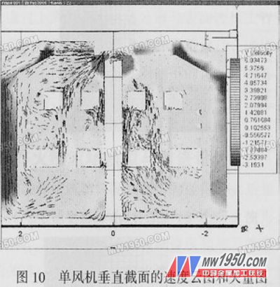
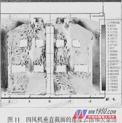
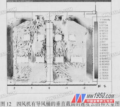
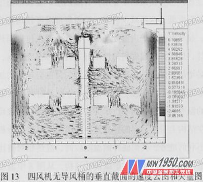
3. Dynamic analysis of flow field in large carburizing furnace We simulated the furnace design of the single fan and the four fan respectively. Figure 10 and Figure 11 show the velocity cloud diagram (including the vector diagram) of the vertical section of the single fan and the four fan in the case of the air guiding bucket. From the distribution of speeds in Figure 10 and Figure 11, when the furnace body adopts the four-fan design, the gas flow velocity of the gear spoke hole is obviously improved compared with the single fan, and the gear tooth is improved. There is basically no major change in the gas flow rate. The carburized part of the gear is mainly the tooth part, so the improvement effect of the design scheme of the four fan is not obvious. Figure 12 and Figure 13 are velocity diagrams (including vector diagrams) of the flow field in the vertical section of the furnace with and without the air duct. It can be seen from the velocity distribution in Fig. 12 and Fig. 13 that the flow velocity of the gas around the gear is higher in the case of the air guiding bucket; and the gas flow velocity around the gear is lower in the case of the airless bucket, especially the lower part. The gas flow velocity around the gear is small. The simulation results show that the use of the air duct can significantly increase the gas flow intensity around the gear and improve the distribution effect of the carburizing atmosphere; without the air bunker, that is, the use of four fans, the situation is not optimistic. There is also a revelation from Fig. 10 to Fig. 12 that the gas flow rate is very large at the position of the holes on the large gear spokes, and carburization is usually not required here, if they are covered during the clamping, It is beneficial to increase the gas flow rate at the gear ring. Previous Next Metal Security Lock,Lamp Box Latch,Lamp Box Lock Door Hardware Co., Ltd. , http://www.hardware-xy.com
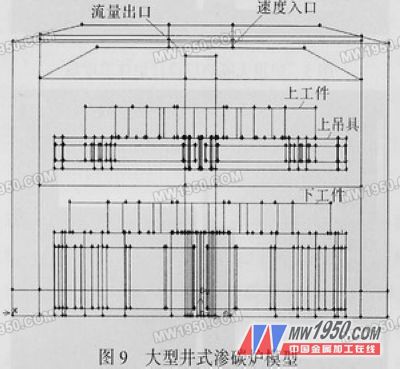
In order to ensure the carburizing quality of large workpieces, in addition to temperature uniformity is an important consideration, the uniformity of carburizing atmosphere is also a major factor, so it is necessary to study the distribution of carburizing atmosphere in the carburizing furnace. In this example, the flow field dynamics (CFD) analysis method is applied to solve the flow field distribution under different design schemes of the large well type carburizing furnace, and the atmosphere circulation under different schemes is compared, which is the furnace body and the loading. The design of the tray provides a reference. Figure 9 shows a large-scale well carburizing furnace model network. 